

C 2.4 POLYPROPYLENE (PP) / KP and MKP
In the book we use the common European abbreviations KP for film/foil and MKP for metallized film.
C 2.4.1 Introduction
Polypropylene (PP) is from a molecular point of view a non-polar dielectric with small losses and a relatively straight and moderate TC. Since the smallest film thickness is approx. 3.5 μm (0.14 mils) and εr ≈ 2.3 the capacitor can not come down to those sizes characterizing PET at low rated voltages. But remaining good characteristics in many applications have brought up PP as a replacement for polycarbonate (PC) and polystyrene (PS), not least as a precision capacitor. PP exists in both foil and metallized design and is adopted for both AC, pulse and transient suppression (X-capacitor) applications. The pulse and X-capacitor designs, however, require a specific metallizing technology.
The MKP design had from the beginning problems with the adhesion between the metallized layer and the plastic film. This problem characterizes non-polar dielectrics consisting of molecules and has caused many problems at, for example, gluing of components to circuit boards. The plastic surface film has to be raised and roughened which among other things can be done by etching, flame exposure, electron irradiation or corona. Today the MKP design is well established and the adhesion problems a passed period.
The demand for filtering / interference suppression of thyristor generated noise voltages has brought forth the same type of large capacitors as shown for PET but here the low ESR losses allow quite different r.m.s. currents, for example at high frequencies.
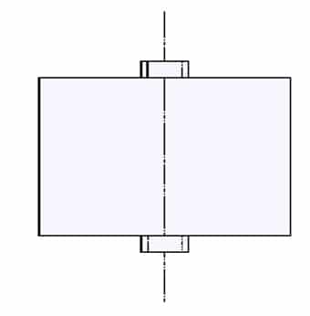

Figure C2-44. Example of a filtering / interference suppression capacitor.
The recommended absolute maximum temperature is +105°C. We recommend max +85°C with the remark that developments of new films is going on to offer temperature range above +105°C as a maximum operating temperature. Current temperature limitations still make PP difficult for chip designs.
C 2.4.2 Temperature and frequency dependencies
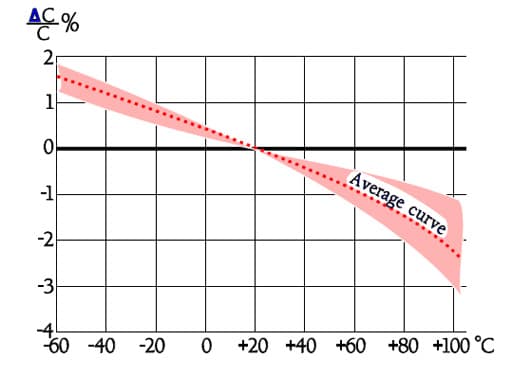

Figure C2-45. Typical curve range for capacitance versus temperature of the KP and MKP design.
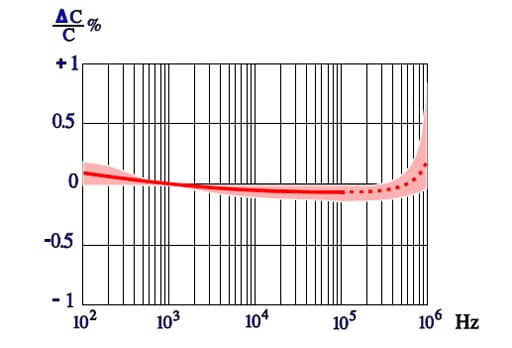

Figure C2-46. Typical diagram of capacitance versus frequency for KP/MKP designs.
The frequency dependence of capacitance for PP capacitors is moderate. In Figure C2-46 the broken part of the curve indicates an increase of capacitance. This increase is not physical but depends on influence from series capacitance measurements according to Formula C1-10.
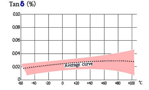

Figure C2-47. Typical curve range of Tanδ versus temperature for MKP and KP.
Note in Figure C2-47 the outstanding low loss factor for PP over the whole temperature range.
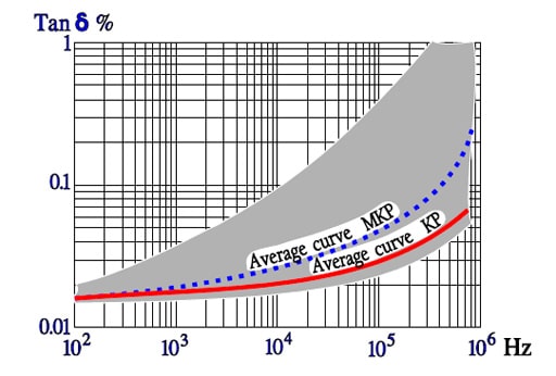

Figure C4-48. Typical curve range of Tanδ versus frequency for KP and MKP capacitors.
The curve area in Figure C2-48 represents capacitance up to some hundreds of nF. The higher capacitance, the greater losses.
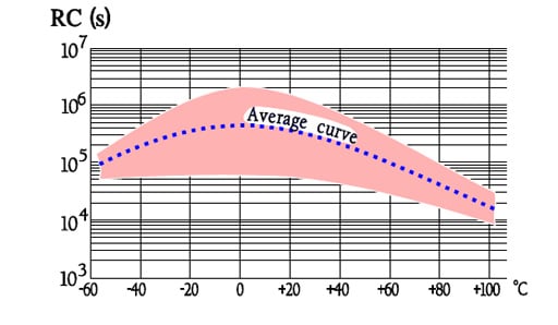

Figure C2-49. Typical curve range showing the IR versus temperature for KP and MKP capacitors.
Designs with foil or hermetic seal have somewhat higher IR than corresponding metallized and plastic encapsulated types.
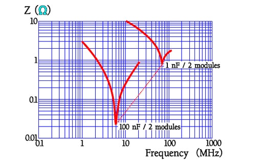

Figure C2-50. Examples of resonance frequencies for 2 modules lead space MKP capacitors.
C 2.4.3 Failure modes
Any characteristic failure mode just for PP capacitors is not distinguishable. Here what was said about PET usually applies.
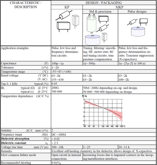
Table C2-5. POLYPROPYLEN (PP) / KP / MKP

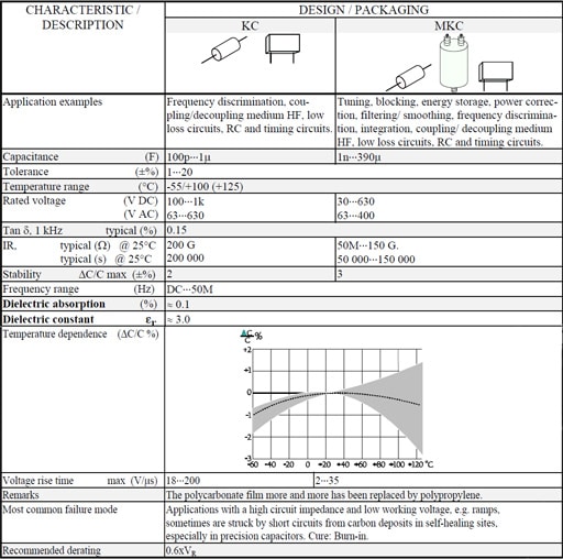
C 2.5 POLYCARBONATE (PC) CAPACITORS / KC and MKC
For a long time the polycarbonate capacitor has been predominant among metallized precision capacitors. Nowadays, however, the MKP capacitor has taken over more and more applications from the MKC. Where one has been able to disregard the TC differences the foil design of the KC often has replaced polystyrene (PS) but also here KP capacitors are replacing those of polystyrene. The manufacture of PC film therefore is declining and, will eventually cease. We shall have a closer look on reasons and characteristics.
C 2.5.1 Introduction
The polycarbonate film is unlike other plastic films prepared from an emulsion that is dried. Its least thickness is stated to 1.5 μm (0.06 mils) and its εr to 3.0 at 1 kHz and room temperature. This film has small dielectric losses, a high IR, a small temperature dependence and a maximum temperature that by many manufacturers was specified to +125 °C. Thus it was rapidly popular, not least in precision capacitors.
Because there is a certain risk of increasing IR failures above +100 °C we recommend this ambient as a maximum or, not more than that of the manufacturer’s data sheet if they specify a lower temperature.
Genuine SMD designs are missing but there are examples of broad spread-out metal strap terminals reminding of the Gull wing design. But check if it is a single source situation.
C 2.5.2 Temperature and frequency dependencies
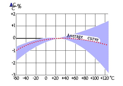

Figure C2-51. Typical curve range for capacitance versus temperature in KC and MKC designs.
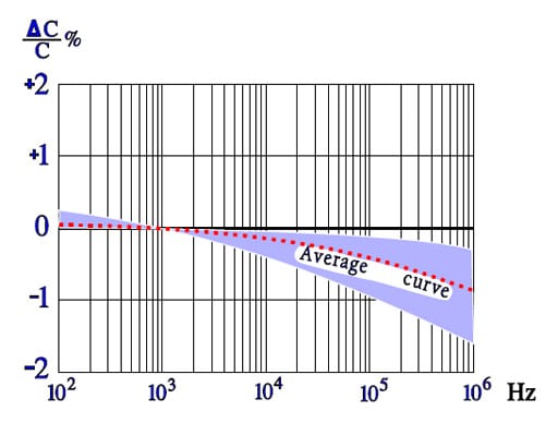
Figure C2-52. Typical curve range for capacitance versus frequency in KC and MKC designs.

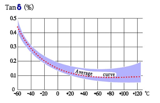

Figure C2-53. Typical curve range for Tanδ versus temperature in KC and MKC designs.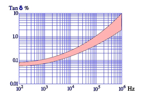

Figure C2-54. Typical dependence of Tanδ versus frequency in KC and MKC capacitors.
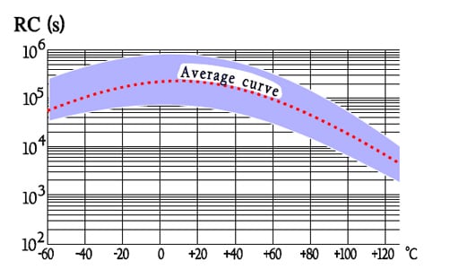
Figure C2-55. Typical function of RC versus temperature in KC and MKC capacitors.
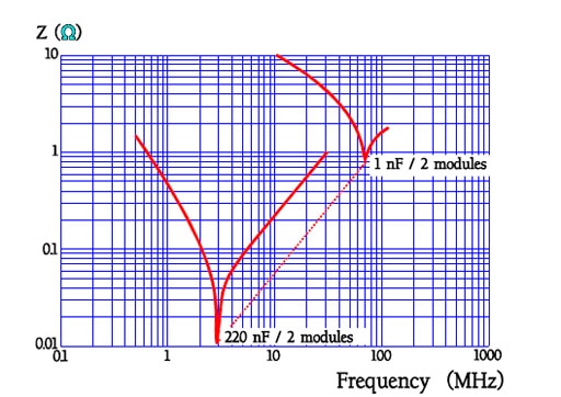

Figure C2-56. Examples of resonance frequencies in MKC capacitors.
C 2.5.3 Failure modes
In 1977-78 some mysterious short circuiting failures were reported from precision capacitors in high impedance low voltage applications. In 1982 a Voyager satellite was met with a failure in a 8 μF/ 75V polycarbonate capacitor. Half-way to Jupiter the IR suddenly dropped from hundreds of MΩ to 2.8 kΩ. All over the world component experts worked with this kind of problem and by and by the picture became clearer. The reasons are described in chapter C2.1.6, The resulting effects of a self-healing.
The issue is a critically high carbon deposit in former self-healing sites, which is connected with the high carbon contents in the polycarbonate film. But the failure only appears in that very narrow application sector where just precision capacitors usually are used, namely at low voltages and in high impedance circuits, e.g. integration and ramp voltages. Even that very low energy needed to burn away the formed carbon string may be missing. The cure is some kind of Burn-in treatment. From a failure rate in the magnitude of, say one per cent, we should get down to or below one per thousand. The most sophisticated (and expensive) Burn-in program we find in US MIL-C-87217. In conclusion it is built on a collection of all those environments which are regarded to release this kind of short circuits: cyclic voltage ramps with polarity changes + gradual temperature fluctuations.
Table C2-6. POLYCARBONATE (PC) / KC / MKC

ABC of CLR: Chapter C Capacitors
Film and Foil Organic Capacitors PP and PC
EPCI licenced content by:
[1] EPCI European Passive Components Institute experts original articles
[2] CLR Passive Components Handbook by P-O.Fagerholt*
*used under EPCI copyright from CTI Corporation, USA
![]()

This page content is licensed under a Creative Commons Attribution-ShareAlike 4.0 International License.
see the previous page:Film and Foil Organic Capacitors PET and PEN
< Page 9 >
see the next page:Film and Foil Organic Capacitors PS,PPS,PTFE,PSU