

Tantalum, MLCC, and super capacitor technologies are ideal for many energy storage applications because of their high capacitance capability. These capacitors have drastically different electrical and environmental responses that are sometimes not explicit on datasheets or requires additional knowledge of the properties of materials used, to select the best solution for a given design.

This paper compares the performance of these technologies over energy density, frequency response, ESR, leakage, size, reliability, efficiency, and ease of implementation for energy harvesting/scavenging/hold-up applications. A brief, material properties benefits and considerations of X5R, Tantalum,
Tantalum polymer, and electrochemical double-layer capacitors is provided. An example of an energy storage circuit problem is provided that has a capacitance and voltage requirement that is not achieved with a single, maximum CV capacitor for any of the relevant technologies. Capacitor banks are built with each technology that are viable solutions.
Design considerations are discussed for optimization of each capacitor bank and analyzed. Results of the analysis will show where each technology excels. This paper should be of interest to component engineers, program managers, and power electronics engineers working on energy harvesting, scavenging, and hold-up applications, due to its impact on system design and performance.
The paper was presented by Daniel West, AVX USA at the 3rd PCNS 7-10th September 2021, Milano, Italy as paper No.4.4.
Capacitors for Energy Storage Applications
Energy Storage Applications
Energy storage capacitors can typically be found in remote or battery powered applications. Capacitors can be used to deliver peak power, reducing depth of discharge on batteries, or provide hold-up energy for memory read/write during an unexpected shut-off. Capacitors also charge/discharge very quickly compared to battery technology and are optimal for energy harvesting/scavenging applications, and depending on power requirements, can replace batteries altogether.
Combining the superior power density of capacitors with a wide operating temperature range, high reliability, low weight, and high efficiency, it is easy to see how capacitor technology is ideal for energy storage applications, but sometimes it is not easy to see which capacitor technology should be selected for energy storage. Capacitor performance across temperature, voltage, frequency, and time should be considered, but this data is not always prevalent on a datasheet. Capacitor specifications of capacitance, DC leakage current (DCL), equivalent series resistance (ESR), size, etc. are typically room temperature measurements under a very specific test condition. Furthermore, energy storage capacitors will often be set up in some parallel/series combination that can pose unique challenges or unexpected behaviour. In short, without enough knowledge of the specific capacitor technology used, there will likely be many design challenges requiring lots of trial and error, to achieve the optimal energy storage capacitor bank.
Capacitor Technology & Selection
Only ceramic, Tantalum (solid electrolytic), and supercapacitor technologies are reviewed in this paper to be concise, but also to present information on energy storage capacitor technologies that may not be as prolific as aluminium electrolytics, and yet not so obscure that it would be unlikely considered for a general energy storage application. Ceramics are ubiquitous and widely used for decoupling and filtering applications, but there are dielectric formulations that can achieve very high capacitance per unit volume (CV), that make them viable for energy storage in addition to their small size and low costs.
Tantalum and Tantalum Polymer (TaPoly) capacitors are also high CV devices, but extremely stable across temperature and voltage. Electrochemical Double Layer Capacitors (EDLC), commonly known as supercapacitors, are peerless when it comes to bulk capacitance value, easily achieving 3000F in a single element discrete capacitor. However, these technologies perform differently based on application details and knowing even an introductory level of materials
and construction helps in selecting the optimal capacitor for a given set of design constraints.
Multilayer Ceramic Capacitors (MLCC)
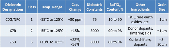
MLCC dielectrics are organized into 3 main classes by the Electronics Industry Alliance (EIA) and the International Electrotechnical Commission (IEC) because there are many ceramic formulas that could realize a capacitor. The classification system is intended to organize the performance of many dielectric formulas by providing its maximum capacitance change within a specific temperature range. With this information, a designer is more prepared to select a ceramic capacitor based on temperature stability, but there is more to consider if the impact of Barium Titanate composition is understood.
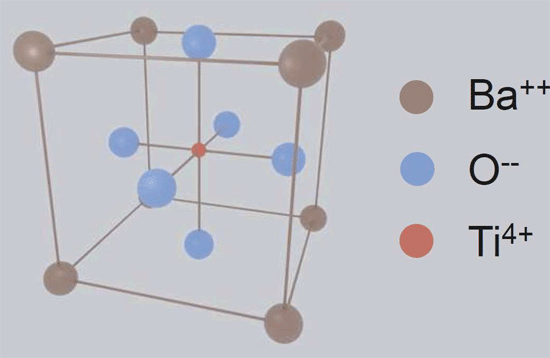
Class 2 and class 3 MLCCs have a much higher BaTiO3 content than Class 1 (see table 1). High concentrations of BaTiO3 contributes to a much higher dielectric constant, therefore higher capacitance values within a given volume, which is great for high CV devices. However, the crystalline shape of BaTiO3 (see figure 1) deforms in the presence of voltage, temperature, and naturally deforms over time. When deformed, the dipole moment of a BaTiO3 crystal is
reduced, limiting the amount in which it can reinforce an electric field, and effectively reduces the capacitance value of the device.
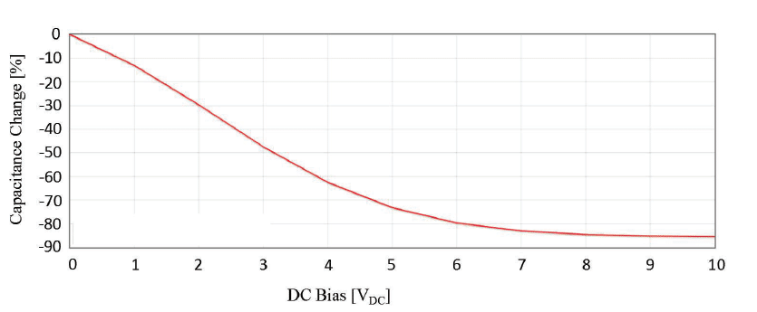
This means for any Class 2 or Class 3 MLCC, the actual capacitance that can be achieved with applied voltage is lower than the specified capacitance value found on datasheets (see table 2). It should be noted that capacitance change of Class 1 ceramics due to voltage bias or aging is virtually zero. The loss or change in capacitance due to temperature, time, and voltage are additive for MLCCs, and must be considered to select the optimal energy storage capacitor,
especially if it is a long life or high temperature project.


Tantalum & Tantalum Polymer
Tantalum and Tantalum Polymer capacitors are suitable for energy storage applications because they are very efficient in achieving high CV. For example, for case sizes ranging from EIA 1206 (3.2mm x 1.6mm) to an EIA 2924 (7.3mm x 6.1mm), it is quite easy to achieve capacitance ratings from 100μF to 2.2mF, respectively. In addition, capacitance values are extremely stable across voltage and temperature range when compared to Class 2 and Class 3 MLCC dielectrics, but an energy storage capacitor selection should not be based on these parameters alone.
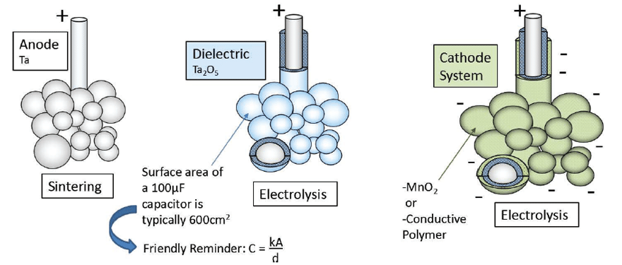
Tantalum and TaPoly capacitor dielectrics are formed by dipping a very porous pellet of sintered Tantalum grains (anode) in an acid bath followed by a process of electrolysis (see figure 2). The oxide (Ta2O5) layer thickness contributes a great amount to the device voltage handling and its overall reliability. It should be noted that the dielectric thickness does have a correlation to the device rated voltage, but this correlation is not standardized and will change based on manufacturer or the intended application that the capacitor is designed for. The cathode is formed by a second process of electrolysis to form either a Manganese oxide (MnO2) layer or conductive polymer layer. From this point, energy storage capacitor benefits diverge toward either high temperature, high reliability devices, or low ESR (equivalent series resistance), high voltage devices.
Standard Tantalum, that is MnO2 cathode devices have low leakage characteristics and an indefinite lifetime2, showing improved reliability the longer it is used, but care should be taken to follow voltage derating recommendations (50%) and manage polarity to preserve the dielectric layer. The conductive polymer cathode systems contribute to very low ESR values that can be up to 1/8 of an equivalent rated MnO2 device, which means 8x power handling capability, but at the same time conductive cathode leakage currents are inherently higher, as seen in the study included in this paper.
The polymer material is hygroscopic and will wear out over time, although much slower than that of Aluminium electrolytics3, but the polymer material also contributes to a benign failure mechanism, and lower voltage derating recommendations (80%), which account for the higher rated voltage devices.

Electrochemical Double Layer Capacitor (EDLC)
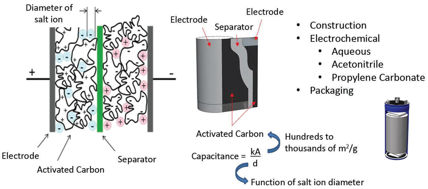
Supercapacitors rely on an electrochemical and a double layer of highly dense, yet porous activated carbon to achieve their extremely high capacitance values. The electrochemical has salt ions that will polarize in the presence of an electric field, providing the bulk charge storage mechanism, and the ions have a very large surface area to be distributed via the activated carbon layers (see figure 3). A typical activated carbon electrode layer will have a surface area of hundreds to thousands of m2/g depending on the design. A pair of activated carbon electrode systems, with a separator in between, would be wound and inserted into can, filled with an electrochemical and sealed and terminated to complete a discrete supercapacitor package. The capacitance values of a discrete supercapacitor can range from a single Farad to thousands of Farads, and the voltage rating would be based on electrochemical properties, as opposed to dielectric thickness like that of ceramic or Tantalum technology.


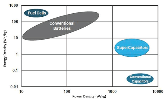
The unique material properties of a supercapacitor give it energy and power characteristics that do not fall under battery technology nor solid-state capacitor technology e.g. MLCCs (see table 3). Compared to batteries, supercapacitors retain much lower levels of energy, but can deliver an enormous amount of power with significantly increased number of charge/discharge cycles than that of batteries. This property makes it ideal for many peak power, remote, battery replacement/supplement, and energy harvesting/scavenging applications. However, typical electrochemical voltage capability is relatively low (compared to traditional capacitors), meaning series/parallel combinations of discrete capacitors would need to be implemented, in addition to considering the environmental effects on supercapacitor life and reliability.
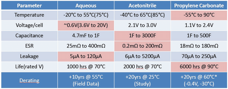
Table 4 shows electrical performance and lifetime at temperature, for three different electrochemical systems. Although aqueous systems have the lowest voltage breakdown specification per cell, the cells are easily stacked into series configurations to achieve higher voltage ratings (up to 20V) without diminished electrical performance and is therefore presented as a discrete device voltage rating, and boasts the lowest leakage currents. Propylene carbonate devices have the widest temperature range, lower derating requirements, and superior expected lifetime performance. Acetonitrile devices are currently the most common technology used for their ability to achieve high capacitance and low ESR. In addition, it has been found that for roughly every 10°C or 0.2V derating that is applied, the expected lifetime effectively doubles4,5, which makes this technology viable for long term applications.

Energy Storage Application Test & Results
Energy Storage Application Test & Results
A simple energy storage capacitor test was set up to showcase the performance of ceramic, Tantalum, TaPoly, and supercapacitor banks. The capacitor banks were to be charged to 5V, and sizes to be kept modest. Capacitor banks were tested for charge retention, and discharge duration of a pulsed load to mimic a high power remote IoT system.
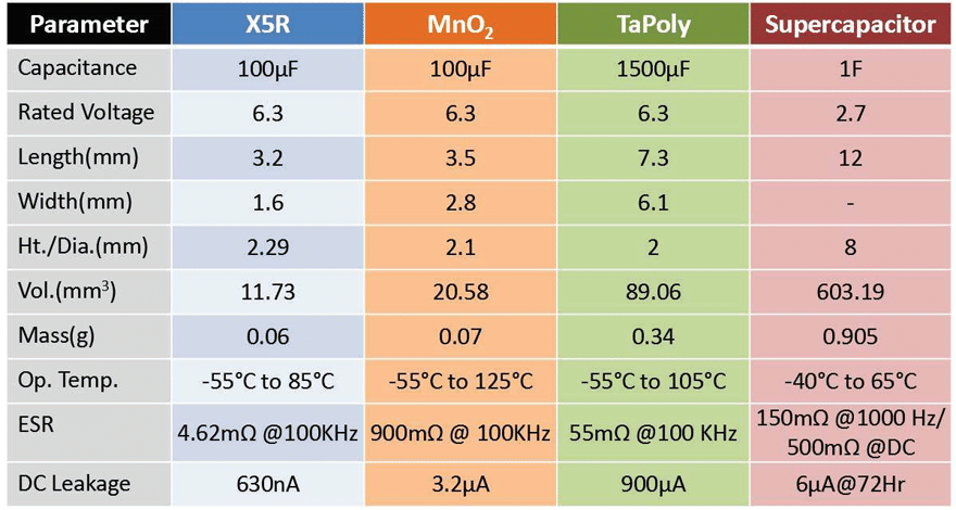
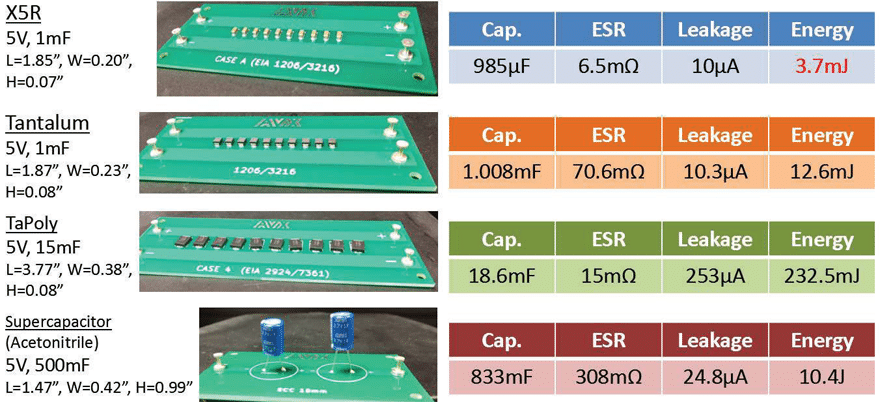
Table 5 displays specifications of the discrete capacitors that were selected for the energy storage capacitor banks. For ceramic technology, an X5R, EIA 1206, 100μF, 6.3V rated MLCC was selected because of its size and high capacitance value. A Tantalum (MnO2) was selected with identical capacitance and voltage ratings, in a similar sized package to get a good comparison of these two technologies. A very large 1500μF TaPoly was selected at the same 6.3V rating, making for a slightly larger capacitor bank, but reviewing the performance of a conductive polymer device at the highest available capacitance at a 6.3V rating is worthwhile. For supercapacitors, the acetonitrile electrolyte system was selected for its low ESR, easy implementation, low cost, and because it is the most common and widely used for modules. A 1F, 2.7V rated, radial leaded supercapacitor device was selected for its small size and would only
require two devices in series to achieve a 5V rated module with no balancing required.

Energy Storage Capacitor Bank Setup and Specifications
Figure 4 provides details of the completed capacitor banks using the four capacitor technologies that were selected. The 5V, 1mF, X5R capacitor bank is the smallest, and has the lowest ESR, but its energy content is the lowest at 3.7mJ. This value is considerably less than what we would estimate using E = 1/2CV2, but when charged to its rated 5V there will be a reduction of capacitance capability because of the DC bias performance of Class 2 MLCCs. It was decided to limit the number of devices to ten in consideration of size for the most part, but it was also known that 1mF would provide enough significant data points during the discharge test.
The Tantalum module is comparable in size and leakage to that of the X5R module, but has higher energy storage capability because of its stability across voltage, but also higher ESR due to the inherently convoluted surface area of the dielectric and cathode interface, which also contributes to the broadband frequency response of Tantalum devices. The TaPoly module takes up the largest surface area but has low ESR because of the conductive polymer cathode system and has the benefits of voltage and temperature stability afforded by Tantalum technology.
The supercapacitor module is the most size efficient when it comes to bulk energy storage, and only two devices were required to achieve an acceptable capacitance and voltage rating. Supercapacitor modules could have been designed with more parallel/series devices with balancing resistors to lower ESR and leakage further but is outside the scope of this paper. The goal is to provide a brief overview of technology performance so that complex scenarios can be expanded on this effort.

Charge Retention Test
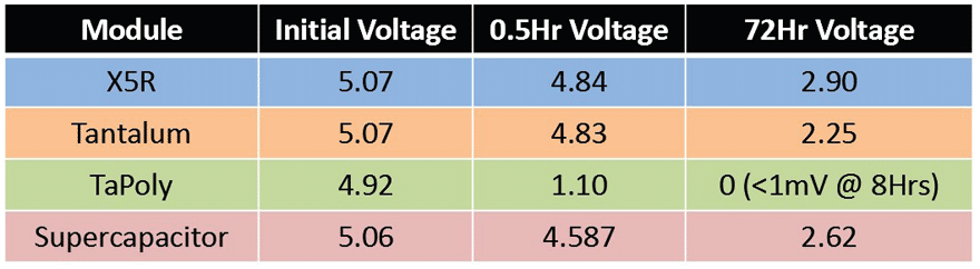
Each module was charged to 5V, removed from power, and monitored for three days to measure the quality of charge retention. This could theoretically account for a remote solar powered module experiencing inclement weather for an extended time. It was observed that the TaPoly module had a higher voltage drop, but was within expectations, due to its conductive polymer cathode, but it is also expected that it will have improved performance in a discharge test. In addition, having capacitors in parallel increases the leakage current of the bank of capacitors. The remaining modules performed comparably after 72 hours, with X5R performing the best which is expected due to inherently high insulation resistance (IR) values of MLCCs. The series orientation of the supercapacitors helps the supercapacitor module in terms of leakage currents, because the IR values would be additive, increasing charge retention performance.

Discharge Test
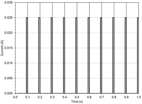
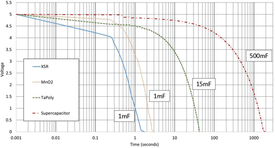
The capacitor banks were charged to 5V for the discharge test and subsequently exposed to a pulsed load with the waveform found on figure 5. Again, the load is to mimic a high-power RF transmission of a remote IoT module. Voltage levels on the capacitor banks were recorded during the test to monitor discharge rate. Figure 6 displays the duration that the capacitor banks could support the pulsed load. For an arbitrary cut-off voltage of 1V, it’s observed
that the supercapacitor bank lasted ~20 minutes, TaPoly ~33s, MnO2 ~2s, and the X5R was just over a second.
Although the MnO2 Tantalum capacitor bank was an equivalent to the X5R MLCC bank, it lasted twice as long, but this is not surprising knowing about the DC bias effects on Class 2 MLCCs. Also, the TaPoly had about a 10% increase in discharge efficiency versus the standard Tantalum bank. And, of course, the supercapacitor bank is enabled by its unique technology to support the system for the longest amount of time. It should be noted the supercapacitor module
was extremely simple i.e. no balancing circuit or voltage monitoring, and that environmental effects were not taken account for, all measurements and test were performed at 25°C. Complex module designs, austere environment or simply applications with low power and duty cycle requirements may not benefit from the use of supercapacitors.


Summary and Conclusions
Summary and Conclusions
In summary, X5R MLCC dielectrics are ideal for small loads where size and cost constraints of a design take priority.
X5R was selected for this study because of its high CV capability, low costs, and availability, but there may be other formulas that are viable for a given design. It is up to the designer to address how well the dielectric will perform in-application due to electrical, mechanical, and thermal stress; data that may or may not be explicit on manufacturer datasheets.
Tantalum (MnO2) capacitors are a good selection for long life applications, because of virtually no wear-out mechanism. These devices need to be properly derated though and polarized to make full use of its high reliability capabilities and will provide an extremely stable capacitance across high temperatures and voltage gradients. Tantalum polymers, as observed by this study, are more viable in Dying Gasp or Last Gasp applications where the power delivery
capacitors are always charged. These are small, high CV, low ESR, high voltage options, great for short burst applications that require efficient power delivery.
Finally, it is easily discernible that supercapacitors are ideal for the broadest range of energy storage applications. They easily achieve enormous capacitance values, easily implemented, have power densities much larger than batteries, and their reliability can be easily managed by proper temperature and voltage
derating. But, because of the relatively low voltage capability (per cell) of the electrochemical systems used, often series/parallel combination modules will need to be created or acquired to achieve a specific voltage rating. If modules are designed in-house, it should be known that modules typically boil down to balancing ESR and DCL performance.
References
[1] Multilayer Ceramic Capacitors Materials and Manufacture; Kahn, Manfred; https://www.avx.com/docs/techinfo/CeramicCapacitors/mlcmat.pdf
[2] High-Reliability Solid Tantalum Capacitors; Fairey, Bob; https://www.avx.com/resources/high-reliability-solidtantalum-capacitors/
[3] Conductive Polymer Capacitors Basic Guidelines; S. Zednicek, J.Petrzilek, P.Vansura, M.Weaver, C.Reynolds; https://www.avx.com/docs/techinfo/PolymerGuidelines.pdf
[4] Reliability of Supercapacitors: Unique Performance at 85°C & Self-Balancing; E.DeRose, B.Knopsnyder, B.Rawal; https://www.avx.com/docs/techinfo/whitepapers/AVX-Whitepaper-Reliability-of-SuperCapacitors-Paper1.pdf
[5] Reliability of Supercapacitors: Long-Term Reliability Test Data; E.DeRose, B.Knopsnyder, B.Rawal; https://www.avx.com/docs/techinfo/whitepapers/AVX-Whitepaper-Reliability-of-SuperCapacitors-Paper2.pdf