

R 4.2.1 Power potentiometers
Power potentiometers are as a rule wirewound. They are wound on a ceramic body and lack, due to heat dissipation concerns, encapsulation in casings or housings. Often they have a touch protection of silicone lacquer, cement or enamel and they are readily used as rheostats. If we turn the shaft of a rheostat towards zero resistance it is not unusual that the current burns off the last turns in the winding if the load impedance is low. Hence, the current in a rheostat must not exceed that of the rated power.
The sliding contact of the wiper sometimes consists of silver. If there are sulfur compounds in the air, for example from oil incineration plants, silver sulfides are formed on the sliding contact. If they are not worn off by frequently recurrent adjustments, the next change of position will cause ESR values going towards open circuit modes. A typical example of a power potentiometer is shown in Figure R4-28.


Figure R4-28. Wirewound power potentiometer.
R 4.2.2 Panel mount potentiometers Type 2
Under this heading are collected wirewounds with bobbins of fiber card or the like and non-wirewounds with resistance elements of molded carbon composition, conductive plastic or cermet applied on substrates of laminated paper (bakelite paper), plastic or ceramics. In order to prevent the potentiometer housing from separating when the shaft is turned, the housing or mounting plate is supplied with an anti-rotation pin that fits in a corresponding hole in the panel.
The most simple carbon potentiometers have a sprayed and dried carbon compound on bakelite paper. After a number of cycles they will meet with contact disturbance (noise) due to wear grooves in the track and wear debris around the wiper. The best rotational life is with the conductive plastic potentiometer. Due to the metal particles in the cermet it develops an abrasive action that wears on the wiper. Therefore the track is often lubricated with a grease of some kind which reduces the wear.
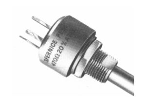

Figure R4-29. Example of a bushing mount potentiometer. Manufacture Vishay Sfernice.
Usually the potentiometers are encapsulated, for more severe environments “hermetically”, which here means seal rings around the shaft. A smaller degree of sealing is offered by the so called “dust-proof” ones. Surface Mount potentiometers exist, both with and without encapsulation. If the assembly process involves washing, the design at least must be tight against rinsing fluids. Otherwise rinsing products like flux residues may be deposited on the track which can lead to severe contact disturbances.
A phenomenon that threatens components with cavities, if they are subjected to temperature changes in humid environments, is the so called pumping effect. An insufficiently sealed potentiometer with large cavities inside the housing is particularly subject to this phenomenon. If humid air in the cavities is cooled the water vapor will condense and create a negative pressure in the cavity at the next temperature rise.
New humid air is sucked in, etc. Instead of having such a half-tight potentiometer, a hole in the bottom of it would be better, so that condensed water could run out…Thus, use qualitatively sealed potentiometers if the environment requires. Especially those with a carbon track, conductive plastic or wire winding are sensitive to moisture. A special type of carbon track potentiometer is the slider pot with a linear motion. It is usually used in audio controls in studio mixer panels.
It is important that the bulk track is molded and thus relatively wear resistant, partly to allow long use, and, partly so that noise producing wear will be prevented. Caution! If one has chosen some type of slider potentiometer it is usually difficult to find any equivalent second source.
Current derating
The current through the wiper should in potentiometers with a carbon or conductive plastic track be kept low in order to minimize noise and wear, preferably values less than 0.25 mA. Wirewound potentiometers, on the other hand, should draw a certain minimum current through the wiper – more than 0.1 mA – in order to reduce noise and contact disturbances. The contact resistance in cermet potentiometers has the sensitivity of the metals to small currents and should likewise carry a certain minimum current. An adequate minimum value might be 25 µA (Reference to Figure R6-15). The data sheets also state a certain maximum current through the wiper, for example, 100 mA at resistances below 100 ohms. At higher resistance values the contact resistance CR increases, which could lead to local overheating if the wiper current is not kept down.
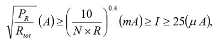
Thus, the wiper current is determined not only by the resistance value but also by nominal power, resistance track material and rotational life (number of shaft turns). In the summary tables we shall describe some guiding formulas for the wiper current I that is confined within certain limits. The highest limit is the maximum power current of the potentiometer, that may be calculated from the equation
[R4-1]: 

Next maximum limit – that never must be greater than the maximum power current – is calculated by means of a formula that contains the rotational life N expressed in number of million shaft revolutions (megarevolutions, “MR”) and the resistance in question expressed in kohms. The result is obtained in mA.


Finally there exists a commonly recommended minimum limit. Example. Suppose a cermet potentiometer with PR = 0.5 W, N = 100 000 revolutions = 0.1 MR, R = 1 MΩ = 1000 kΩ and the minimum limit for cermet = 25 µA. If we insert 0.1 and 1000 respectively in the applicable formula

we obtain 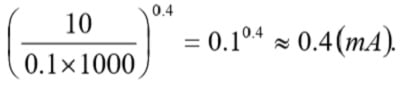

This value is well below the absolute maximum current derived from 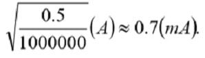

Thus the wiper current should be adjusted to lie between 0.4 mA and 25 µA.


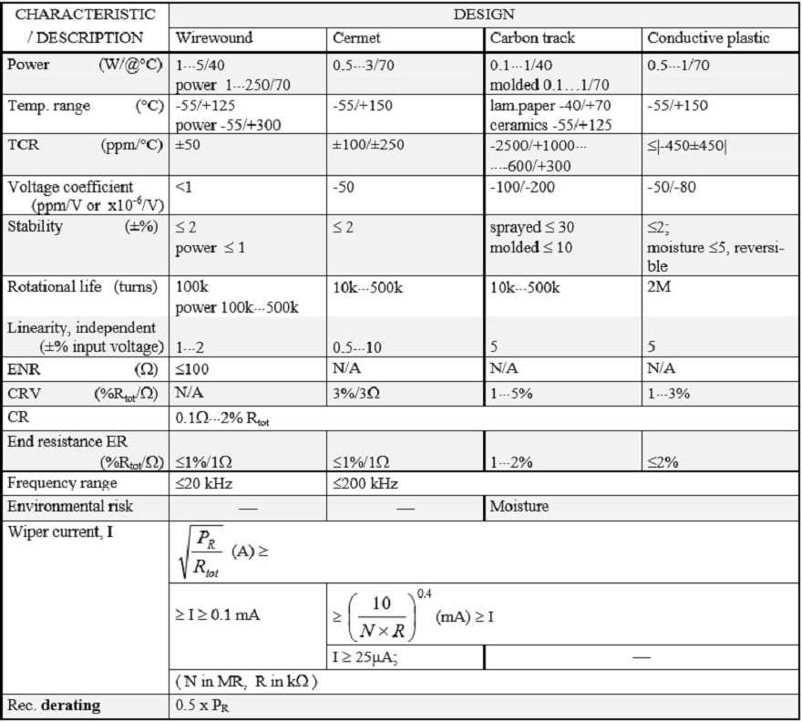

Table R4-1. TYPE 2 POTENTIOMETERS
ABC of CLR: Chapter R Resistors
Potentiometers – TYPE 2 POTENTIOMETERS
EPCI licenced content by:
[1] EPCI European Passive Components Institute experts original articles
[2] CLR Passive Components Handbook by P-O.Fagerholt*
*used under EPCI copyright from CTI Corporation, USA
![]()
This page content is licensed under a Creative Commons Attribution-Share Alike 4.0 International License.

see the previous page: Potentiometers – Basic Principles
< Page 9 >
see the next page: Precision Potentiometers, type 1