
")
SMD NiZn Ferrite Core Storage Choke
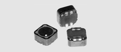
SMD storage chokes with highly dynamic and low loss NiZn ferrite cores (such as Würth Elektronik WE-PD series) are suitable as chokes in switching control applications up to a clock frequency of approx. 10MHz and offer high current loading capacity and low DC resistances.
There are a multitude of construction types available for the different types of application:
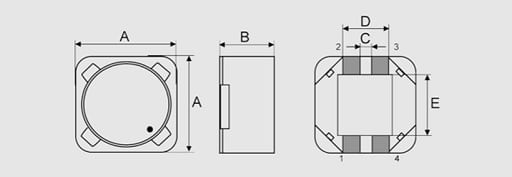
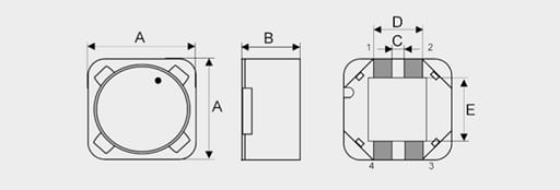
• Magnetically shielded series WE-PD and WE-PD3
• Unshielded versions series WE-PD2 and WE-PD4
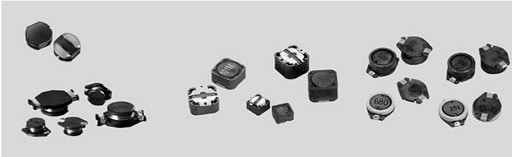

Fig. 2.45: SMD power inductors WE-PD
Data book specifications
Inductance L: Different measurement conditions apply for the different construction series. The inductance is stated at a certain test frequency and measurement voltage (see data sheet).
Current rating IN: The current rating of the inductor is specified as the DC current at which inductor exceeds the permitted tolerance limits (DL) or the self generated heating (DT) exceeds a certain limit. The smaller of the currents defined by the two conditions is termed the current rating of the inductor. This is how ever not the saturation current, which is higher than the current rating.
DC resistance DCR: The windings resistance value is measured with an ohmmeter at an ambient temperature of +20 °C. The test current for resistance measurement is a small DC current, which does not lead to a significant temperature increase in the wire. As values in the milliohm range are measured here, a 4-wire measurement must be made to minimize measurement errors.
Operating temperature: The ambient temperature when operating the SMD NiZn series of storage chokes at full current rating load should generally range from –40 °C to +85 °C. The self-heating of the component must be taken into account at higher ambient temperatures in order that the permissible solder joint temperature is not exceeded or the wire insulation damaged. The wire used can withstand a temperature of up to +150 °C. The ferrite core itself may be used over a far greater temperature range (approx. –50 °C to +250 °C [Curie temperature]). However, in this case, the tolerance limits of the inductor may be exceeded due to the temperature dependence of permeability.
Operating temperature = ambient temperature + self-heating < +125 ºC
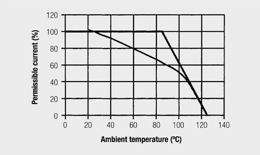

Fig. 2.46: Derating curve of NiZn SMD storage choke (source: WE-PD datasheet)
The above curve assumes that self-heating is permissible up to a maximum temperature sum (component + ambient temperature) of +125 °C. The current must be reduced above an ambient temperature of +85 °C. The curve below is intended for critical applications, in which the coil itself should only generate a small amount of self-heating.
Insulation resistance: The insulation resistance between windings and coil core is more than 100 MΩ for a test voltage of 500 VDC<sub>DC</sub>.
Saturation current Isat: The saturation current is the DC current at which the zero current inductance is reduced by a certain percentage.
The percentage of inductance decrease is however not standardised and can be defined differently for each package type. In datasheets – and especially when comparing data from different manufacturers – very close attention must be paid to the definition point. A printout of the measurement curve “Inductance versus DC premagnetization” is better still. Here the user can, for example, check in detail how the inductor behaves in the case of overload or at the moment it switches on. An example for a standardised curve is shown in Figure 2.47.
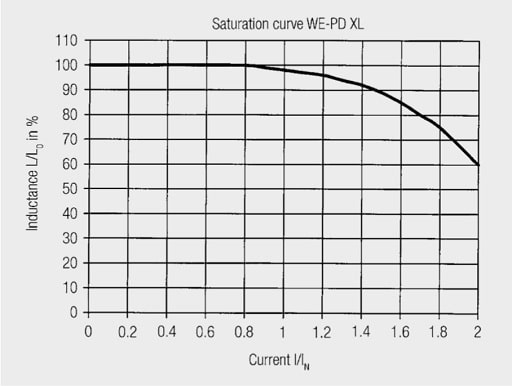

Fig. 2.47: Standardised curve of NiZn SMD storage choke (source: WE-PD datasheet)
Volt-µsec product: As a result of their effective magnetic area Aeff, storage chokes can only be driven to a maximum value – the so-called Volt-µsec product.
The following calculation rule applies for the step-down controller to determine the necessary Vµsec product of storage chokes:


with Et = Vµsec product, Uin(max) the maximum input voltage in Volts, Uout the output voltage of the controller and f the switching frequency in Hz.
With increasing switching frequency, the necessary Vµsec product of the storage choke becomes lower; however, with increasing input voltage it becomes higher. This relationship is again illustrated in Figure 2.48 below.
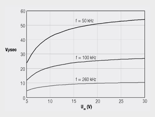

Fig. 2.48: Vµsec product with variable input voltage and different switching frequencies for the step-down controller
Practical tips:
For some types in the SMD NiZn SMD chokes WE-PD series there is also information on the Vµsec product in Table 2.27. If this information is missing, it can be read off from the measurement curve “Inductance versus DC current premagnetization”. Here you locate the inductance plateau where you read off the associated current and residual inductance values and calculate the Vµsec product as follows:


With Lres in µH and Imax in A.
For ferrites, the saturation curve shows a very steep decline beyond a certain DC current value (“hard saturation”). For this reason it is recommended to reduce the Vµsec product calculated in this way and therefore to then optimise inductor selection.
Ferrite storage chokes


Iron powder core storage chokes, Superflux, WE-PERM etc. have a constant decrease in inductance due to the DC-premagnetization (soft saturation).
As a rule:


NiZn storage choke core material parameters
The NiZn (WE-PD) core material parameters are described by the following power loss formula:


The corresponding curve is shown in Figure 2.49.
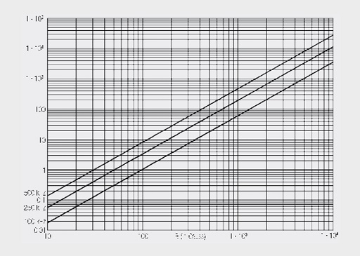

Fig. 2.49: NiZn power ferrite core material losses (WE-PD) (1 Gauss = 10-4 T)
Calculation of storage choke power losses on the basis of the following empirical formulas:


with
ΔI = ripple current (peak-peak) in A due to the inductance; Imax table value read from Table 2.27 or from the measurement curve L=f(IDC).
Power loss and temperature increase in the component
Now the power loss can be approximately determined, the question arises of the temperature rise of the component in operation. Measurement curves can be generated for the rise in temperature of the components with DC currents. Here the questions are to be resolved:
• How was the component measured? – mounted on a PCB with a lot of copper (= cooling element!)
or
– only the component via a thin and poor heat-conducting connection
• After what time was the temperature read off from the component • (thermal time constant!)
The following approximation formulas can be useful in the design phase; however they do not obviate measurement under real operating conditions.
Determination of total power loss in the storage choke:
a) Copper losses:

b) Core material losses from empirical formulas
This results in the total power loss (without further losses such as the skin effect etc. …):


Practical tip:
Temperature increase in the component (large surface)


with Ptot in (W) and the surface area A in (mm2) The following approximation formulas for temperature increase can be specified for the NiZn power ferrite core (WE-PD) and double chokes with two separate windings (WE-DD) storage chokes:
WE-PD type „XS“, WE-DD „XS“:


WE-PD type „S“, WE-DD „S“:


WE-PD type „M“, WE-DD „M“:

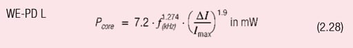
WE-PD type „L“, WE-DD „L“:


WE-PD type „XL“, WE-DD „XL“:


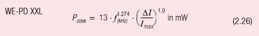
WE-PD type „XXL“, WE-DD „XXL“:

• Suitable for switching regulator IC’s from National Semiconductor, Linear Technology, Maxim, etc.
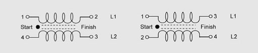
NiZn power ferrite core double chokes
NiZn power ferrite core double chokes with two separate windings (WE-DD series) expand the standard spectrum of storage chokes with more features.

Type S, M

Type L, XL

![]()

Type S, M Type L, XL

Tab. 2.28: Picture and characteristic data of some shielded power transformers (source: WE-DD datasheet)
Features:
Two separate windings on a common ferrite core
- Available in a 1 : 1 winding (standard), but also in other winding ratios (customer-specific)
- Bifilar winding for minimal stray inductance / high coupling factor • (k ~ 0.985 … 0.990) or separate layer winding with increased leakage inductance
- Operating voltage up to 80 VDC
- Isolation voltage 100 VDC max
Applications:
- SEPIC switching controllers (functional principle – see Chapter III/7.4)
- CUK switching controller (switching controller with negative output voltage)
- Switching controllers with second, unregulated output voltage (auxiliary voltage)
Operating temperature:
The ambient temperature of the WE-DD double choke under full rated current load must be between –40 °C and +85 °C. The self-heating of the component must be taken into account at higher ambient temperatures in order that the permissible solder joint temperature is not exceeded or the wire insulation damaged.
The wire used can withstand a temperature of up to +150 °C. The ferrite core itself may be used over a far greater temperature range (approx. –50 °C to +250 °C [Curie temperature]). However, in this case, the inductance tolerance limits may be exceeded due to the temperature dependence of permeability.
Datasheet information:
Electrical characteristics
![]()

Tab. 2.29: Electrical characteristics of the shielded power transformers WE-DD
Rated current: In contrast to other double chokes on the market with datasheet specifications unsuitable in practice, we use a very conservative method of determining the rated current. The self-heating for the pair of windings passing maximum current should not sum to more than +40 °C.
So the rated current is determined for each winding, which passes current on its own, leading to a temperature increase of up to +20 °C and is specified as IN1 and IN2 respectively. If both windings pass their rated current at the same time, this leads to self-heating totaling +40 °C.
DC resistance: Correspondingly, the specification for the winding resistance of the two individual windings is found from individual measurements. Attention: Please compare the datasheet specifications carefully – often the parallel configuration of the two windings is found in the literature as rated current / DC resistance, which suggests a higher rated current and lower DC resistance. In practice this is of course, not the application for this series of chokes!
Saturation current: In the case of the double choke with the same inductance, it is sufficient if just one of the windings carries the saturation current. The second winding is inevitably reduced in its inductance. The value is identical for the same inductance; the saturation current per winding is specified for dissimilar inductance values.
For all other calculations, revert to the formulas and information in the chapter WE-PD (such as core losses, estimation of self-heating, etc.).
TPC “Tiny Power Choke“ SMD storage chokes
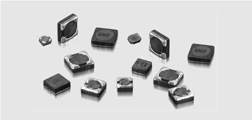

Fig. 2.50: SMD Power Inductor WE-TPC
TPC “Tiny Power Choke“ of storage chokes (WE-TPC) is usually for applications for which the packing density and the package height is important. This design enable to produce the smallest wire-wound inductors in dimensions such as 2.8 x 2.8 x 1.0 mm.
These chokes are mostly used for switching controllers that have several outputs integrated in one IC, e.g. LTC3544B. This IC has 4 outputs at which different voltages, output currents and switching frequencies are adjustable.
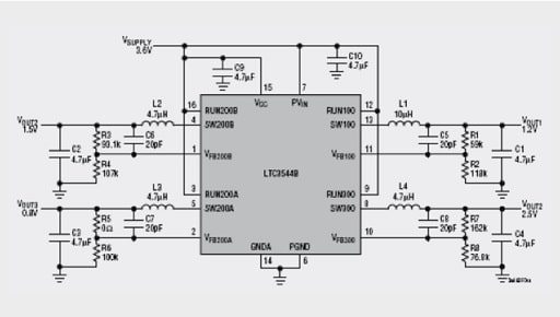

Fig. 2.51: Circuit LTC3544B
The core material used for the WE-TPC series is NiZn and is therefore suitable for switching frequencies up to 10 MHz. The saturation current is defined as a –35% inductance drop in relation to the zero current inductance, which is usually typical for inductances in this small package.
The WE-TPC series is magnetically shielded and therefore especially suitable for switching controllers in mobile applications.
SMD high-current inductors
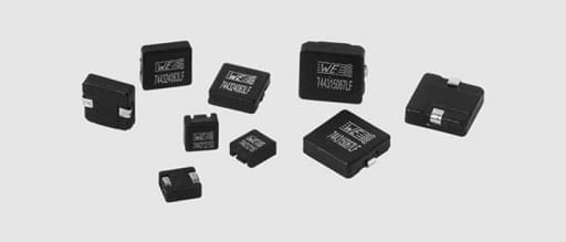

Fig. 2.52: SMD High current inductor (WE-HC series)
Laptop computers and motherboards of modern computers are equipped with processors, whose clock frequencies may be 1 GHz or more. Processor manufacturers rely on low supply voltages in order to maintain losses in integrated circuits within tolerable limits and to attain the required switching speeds. These lie between 1 … 3.3 Volts depending on the processor generation.
Components require large currents at the same time. Current inputs of up to 60 A per processor are not a rarity and cannot be handled by well known switching regulators. The so-called multiphase switching converters fulfill the intelligent power management concept required. Because of the high switching frequency and the output current requirements, one needs only small inductances with high current capability and low losses. SMD high-current inductors are suitable for these applications.
The core material used for WE-HC series is WE-Superflux and is based on a special high- purity alloy of various types of iron powders, which shows significantly lower core losses than conventional iron powder cores. Core losses are nearly as low as those of MPP cores, however, the WE-Superflux material can be operated up to frequencies of over 1 MHz. At the same time, the costs of these cores are lower than those of MPP and CoolMµ® cores.
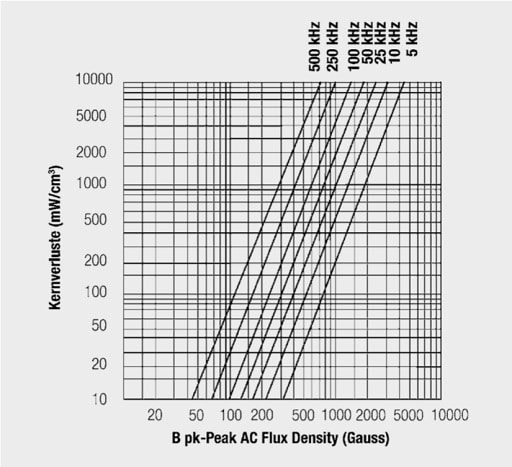

Fig. 2.53: Core power loss of Superflux material WE-HC
Thermal aging: Thermal aging can lead to the destruction of the organic binder used, especially at high operating temperatures with standard iron powder material. A thermal avalanche effect can consequently occur, which may finally destroy the core material. For standard iron powder materials and those not thermally treated for reasons of their production process, the rule of thumb applies that the maximum temperature of +125 °C measured at the component should not be exceeded for a prolonged period.
There is no thermal aging for the material used here and now also available for ring cores – Superflux 200.
Thanks to the polymer binder specially developed for this purpose, the core material is suitable for temperatures up to +200 °C. The maximum operating temperature can even be raised to +320 °C for special applications.


Fig. 2.54: Core material losses against operating hours (no thermal aging identifiable)
WE-HCA core material: WE-HCA, the new high current inductor series from Würth Elektronik, has again been optimized for core loss compared with the WE-HC series. The core material WE-PERM can be used for switching frequencies above 1 MHz. This series also uses rectangular flat wire, which proves to be a major advantage over conventional round wire designs in terms of AC resistance loss.
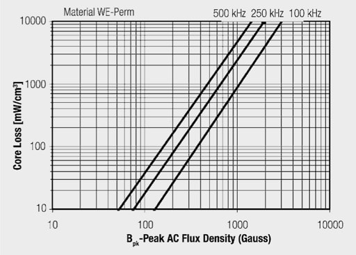

Fig. 2.55: Power core loss of the material WE-PERM of the WE-HCA
A flat wire (Figure 2.56) inside the choke is used in place of the conventional round wire. Flat wire windings offer the following advantages:
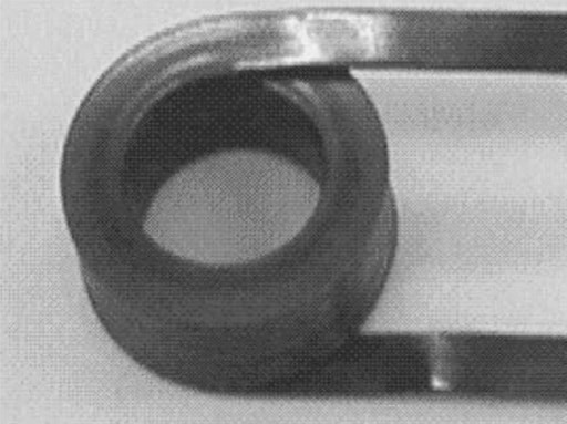

Fig. 2.56: Flat wire winding
Large wire surface – thus low high-frequency losses (skin effect)
- Low winding capacity – hence high self-resonant frequency
- Low DC resistance – thus low self-heating at high prolonged currents
- High packing density and therefore smaller component size than comparable chokes with round wire (Figure 2.57)
- High operating temperature up to max. +150 °C
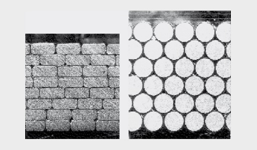

Fig. 2.57: Comparison of packing density for equal inductance between flat wire and round wire windings
Through the combination of WE-Superflux low-loss core material and flat wire windings inside the core, a series of currently seven SMD high-current inductors is created with the following characteristic data:
The size of the component base is 6.6 x 7.3 mm2, 10.5 x 10.0 mm2 or 13.5 x 12.8 mm2 with a height of 3.4 mm to max. 4.9 mm.
The values specified in the data sheet are:
- Open-circuit inductance L0, tested at 100 MHz with 0.25 VAC
- Inductance rating LN at current rating IN and self-heating < +50 °C
- Min. inductance at max. current Imax and self-heating < +100 °C
- Min. DC windings resistance DCRmax at Ta = +25 °C
Figure 2.58 shows the typical behavior of this high-current inductor using WE-HCA the example of the 0.82 µH choke of component size 13.2 x 12.8 x 6.2 mm.
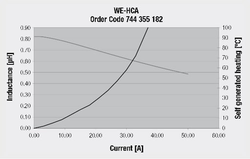

Fig. 2.58: Inductance curve and self-heating against current
The component has an inductance of 0.65 µH at the specified rated current of 27 A and demonstrates typical self-heating of +50 °C. The inductance is very stable under current load; the limiting factor is the self-heating of the component. Even at a current load of 50 A the inductance does not drop more than 30% from the open-circuit inductance. The self-heating is well over +100 °C, however.
Conclusion:
The WE-HC series represents a highly dynamic and robust series of storage chokes, especially suited for use in high-current switching converters and multiphase or polyphase converters. Additional application areas are in high-current interference suppression chokes and as a replacement for rod core chokes.
Radio interference suppression choke WE-FI
Toroidal cores of radio interference suppression chokes are made of compacted iron powder and have a very low stray field. High current loading capacity is achieved through high saturation magnetization.
The useable maximum upper frequency range of this component extends from a few MHz to approx. 30 MHz depending on the type.
The impedance-phase curve against frequency of a typical toroidal core choke is shown in Figures 2.59 and 2.60.
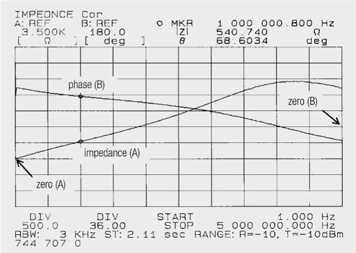

Fig. 2.59: Impedance and phase of the toroidal core choke (100 µH) against frequency (0 MHz–5 MHz)
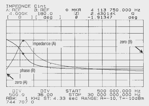
Fig. 2.60: Impedance and phase of the toroidal core choke (100 µH) against frequency (0.5 MHz-30 MHz)
It may be seen from Figure 2.60 that the resonant frequency is at 4.1 MHz. Above 4.1 MHz the capacitive character of the choke predominates, at 30 MHz the impedance has fallen to approx. 200 Ω. The impedance is almost linear (Figure 2.59) up to the resonant frequency of 4.1 MHz.
Due to the frequency dependence of complex permeability, calculations are only feasible in limited frequency bandwidths and sufficiently far (in the linear range) below the resonant frequency. Figure 2.61 shows the equivalent circuit of the choke in the 25 kHz to 1 MHz range, Figure 2.62 the equivalent circuit in the 1 MHz to 5 MHz range. The values were found using an impedance analyzer, calculating on the basis of the components’ equivalent circuit. Due to high non-linearity, the equivalent circuit can be simulated over a wide frequency range with just 3 components.
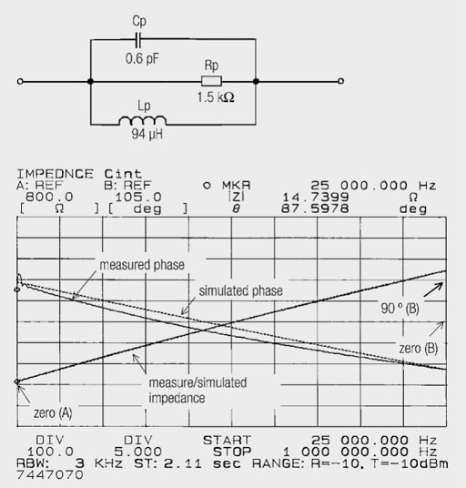

Fig. 2.61: Equivalent circuit with associated measured and simulated impedance – phase curves
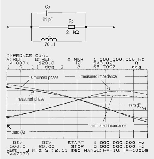

Fig. 2.62: Equivalent circuit with associated measured and simulated impedance – phase curves
From the measurement curves impedance and phase an increase in eddy-current losses and a decrease in the complex permeability can be seen.


the impedance can be calculated as a function of frequency. The broken line in Figures 2.61 and 2.62 are the simulated curves with the values given by the equivalent circuits. It shows that without considering the complex permeability and its frequency dependence, the calculation can be performed with limited accuracy.
Practical tip:
Here another word on the saturation of the ferrite ring: The effective core cross-sectional area is inversely proportional to the saturation current and proportional to the impedance. This means that wherever possible, the larger core cross-section area should be chosen.
ABC of CLR: Chapter L Inductors
Power inductors 2
EPCI licensed content by: Würth Elektronik eiSos, Trilogy of Magnetics, handbook printouts can be ordered here.
![]()
This page content is licensed under a Creative Commons Attribution-Share Alike 4.0 International License.
