

Which parasitic parameters are there in the transformer and how can they be measured and subsequently represented in a simulation model? We want to investigate this on the basis of a transformer and investigate using LTspice.
“Ideal” transformer models are usually used to make it as easy as possible for the developer and to reduce the computation time in LTspice. Only the inductance values for the primary and secondary are required here, as well as the coupling factor K (here in statement K1 Lp LS set to 1 = ideal).

The simulation results are far closer to practice if the coupling factor is already taken into consideration:


because transformers have stray inductances of 2% ~ 8% depending on the construction.
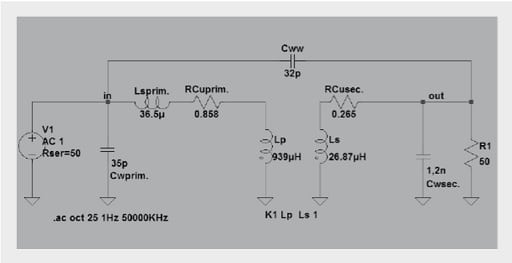
We use the following equivalent circuit for further consideration and to determine the parasitic elements:

Cww: winding – winding coupling capacitance
Cwprim: primary-side winding capacitance
Cwsec: secondary-side winding capacitance
Lsprim: total stray inductance (primary + transferred secondary stray inductance)
RCuprim: primary Cu resistance
RCusec: secondary Cu resistance
Lp: primary inductance
Ls: secondary inductance
The given parameters are: turns ratio → 6.11 : 1, resistance of the windings (1–4) and (5–8), the primary inductance, Lp.

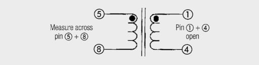
Measuring the primary and secondary inductance
To measure the primary and secondary inductance, the respective winding not measured must remain open. An inductance of 26.87 µH (100 kHz/100 mV) was measured between pins 5/8 and 939 µH (100 kHz/100 mV) between pins 1/4.

The turns ratio n
The turns ratio n can be calculated as follows:


For Lp = 939 µH and Ls = 26.87 uH the calculated turns ratio is 5.91.
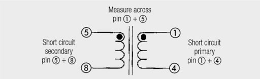
Total stray inductance
Primary stray inductance and transferred secondary inductance can be measured by short-circuiting the secondary winding (pin 5/8) and measuring between pins 1/4.


The result for Lsprim is 36.5 µH
Please note:
The stray inductance is as well in series with the transmission path. The stray inductance describes that part of the magnetical field, which is not enclosed from the respectively other winding and therefore contributes not to the coupling. The stray inductance results simply from the mechanical arrangement of the windings against each other. A decrease of the stray inductance comes along with the increase of the coupling capacitance. The total stray inductance (primary inductance + transferred secondary stray inductance) is measured by measuring at short circuited secondary winding (Please note: To not distort the measurement result a low impedance short circuit is necessary) .
Many applications demand as small a stray inductance as possible. It can be minimized using various winding techniques. The windings should be as wide as possible. A sandwich construction also helps, as in the case of the proximity effect. However, these techniques increase the coupling capacitance between the primary and secondary sides.
DC current winding resistances
RCuprim and RCusec between pins 5/8 and 1/4 respectively can be measured with an ohmmeter (e.g. Metra Hit 27I).
RCuprim: 265 mΩ and RCusec: 858 mΩ
Coupling capacitance
Additional parasitic parameters include the coupling capacitance (capacitance between the primary and secondary sides) and the winding capacitance (capacitance between the turns of a winding).
The influence of coupling capacitance on the circuit can be reduced by shielding windings between the primary and secondary sides. However, minimization of the coupling capacitance by winding in several sections or by inserting thick insulation between the primary and secondary side directly causes an increase in stray inductance.
The coupling capacitance can be measured directly. The winding capacitance is measured indirectly via the resonance between the main inductance and the capacitance. An LCR bridge is used to measure from winding to winding, in this case between pins 1/5. For measurement reasons both windings should be separately short-circuited so the measurement result is not distorted.

Cww: 32 pF
Winding capacitances
The winding capacitances can only be determined indirectly from the resonances with the main inductance (Lprim/Lsec). The impedance with the secondary side “open” is measured with an impedance analyzer. The winding capacitance of the primary side is then calculated from the resonant frequency.

The resonant frequency is 875 KHz, the measurement resulted in Lprim with 939 µH.


Lprim main inductance
Cw winding capacitance
f resonant frequency
Rearranging the formula for Cwprim results in Cwprim 35 pF and for Cwsec 1,2 nF
The same approach is also taken on the secondary side.
This produces the following simulation equivalent circuit:

The simulation then produces the following transfer frequency response for the WE Midcom transformer:

The discrete equivalent circuit can presented in further simplified form, because LTspice offers the option of including the coupling factor, RCuprim, RCusec; Cwsec and Cwprim in the components Lp and Ls, and of defining the stray inductance through the K statement.

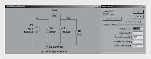
In this case: Parallel capacitance corresponds to Cwsec.
Series resistance corresponds to RCusec.
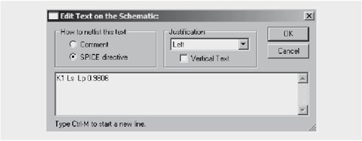
The coupling factor is calculated from:


(with Ls: 939 µH; Lssec:36.5 µH) and then enter in the LTspice text editor as SPICE DIRECTIVE.

Simulated transformer frequency response in LTspice

Further calculation formulas for the equivalent parameters for the model with main inductance Lm:


From this follows for the different inductances:


The values for the resistances are determined by simple measurement with the ohmmeter. This model does not consider core losses, any capacitances or the frequency dependence of resistances due to the skin and proximity effects.
ABC of CLR: Chapter L Inductors
Transformer: Parasitic parameters and equivalent circuit
EPCI licensed content by: Würth Elektronik eiSos, Trilogy of Magnetics, handbook printouts can be ordered here.
![]()
This page content is licensed under a Creative Commons Attribution-Share Alike 4.0 International License.

see the previous page: EMC ferrite equivalent circuits
< Page 9 >
see the next page: Simulation with LTspice