

This article is introducing polymer aluminum electrolytic capacitors technology that operates reliably at high voltages at 450 V. This will allow polymer aluminum electrolytic capacitors to compete with film capacitors as DC-link in power converters in electrical vehicles.
The paper was presented by Shova Neupane, Centre for Industrial Electronics, SDU University of Southern Denmark at the 4th PCNS 10-14th September 2023, Sønderborg, Denmark as paper No. 4.4.
Abstract:
It has been shown that the use of Aluminium electrolytic capacitors as DC-link capacitors instead of the more traditional metalized film capacitors can lead to ultra-compact integrated inverter designs.
However, the high ESR of traditional aluminum electrolytic capacitors leads to increased self-heating and decreased ripple current handling. To overcome this issue, the poorly conducting liquid electrolyte for traditional electrolytic capacitors, can be substituted for better conducting material.
For lower voltages PEDOT: PSS-based electrolytes have been successfully developed providing significantly better ESR and current handling. This technology however has so far not reached the operating voltages that the automotive industry desires for DC-link capacitors in power converters in electric cars.
Developing this technology to operate reliably at voltages at 450 V will allow polymer aluminum electrolytic capacitors to compete with film capacitors as DC-link in power converters in electrical vehicles [1-4].
In this work, we build up an encapsulated capacitor element by using our standard electrolytic capacitor (e-caps) preparation method [4]. The lifetime behavior (aging test) of the successfully prepared e-caps is under measurement from 08/09/2022 and surviving till date 10/11/2022 with 450V at 105℃.
X-ray tomography measurement was done before the aging test in order to know the integrity of the encapsulated e-caps. Leakage current, capacitance, and resistance were measured at regular intervals throughout the lifetime study.
Introduction
The capacitors device was prepared with especially doped PEDOT:PSS (Poly(3,4-ethylenedioxythiophene)-poly(styrenesulfonate)). PEDOT:PSS is a conjugated semiconducting polymer prepared by doping cationic poly(3,4-ethylenedioxythiophene) and poly(4-styrenesulfonate) anion. The structural formula of the PEDOT:PSS molecule provides electrical conduction by delocalized π-electrons in molecular orbitals along the polymer’s conjugated backbone, analogous to a onedimensional band.
The morphological models of PEDOT: PSS grains at different temperatures from combined transmission electron microscope (TEM) and atomic force microscope (AFM) measurements.

The typical diameter of PEDOT:PSS grains is 40-60 nm with a PSS-rich shell thickness of 5-10 nm. The inset in the upper corner of Fig. 1 depicts two regimes of hydrogen bonding in PEDOT:PSS. This grain structure means PEDOT-PSS is a good candidate to improve the ESR behavior of aluminum electrolytic capacitors, providing a factor of 3 lower ESR values if compared to classical electrolyte solutions at higher switching frequencies (> 20 kHz) and at high temperatures.
This feature may appear due to the inter-grain charge transfer, and very little charge transfer occurs at high frequencies that lead to conduction in the grains. A detailed study of this phenomenon is yet to be done.
Experimental methods
Highly oxidized aluminum foil prepared under high voltage was used as the anode, and unoxidized Al foil was used as a cathode, provided by TDK. Two different PEDOT: PSS with special additives were used separately as an electrolyte in this work. The first one is provided by Heraeus and is named PEDOT-PSS1. The second one is provided by one of our collaborators and is named PEDOT-PSS2. The name of the second collaborator is not disclosed here due to the company privacy policy.
The PEDOT: PSS was prepared in an aqueous solution, and specific additives were used for better impregnation and voltage handling, according to the provider. PEDOT-PSS was used in this work without further modifications.
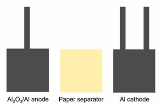
The anode foil was further treated in an acidic electrolyte by applying a constant DC current with a high voltage to regrow and improve the performance of the oxide in the homemade twoelectrode electrochemical setup. Both cathodes and anodes were separated by off-the-shelf capacitor paper, as shown in Figure 1. The prepared device testing was performed via the production of model capacitor stacks consisting of one 20 cm2 anode foil sandwiched between
two cathode foils. The detailed device assembly and test preparation are explained elsewhere.


The prepared electrolytic capacitor (e-cap) was encapsulated in an aluminum can with polyurethane formed from WEVOPUR 552 FLS resin and WEVONAT 300 hardener (supplied by Wevo-Chemie GmbH), as shown in Figure 2.
The resin survives up to 130°C and is designed for high-voltage applications. The capacitance and ESR of the freshly prepared ecaps were measured with an LCR meter manufactured by Keysight (model no E4980AL) in the frequency range from 20 Hz to 1 MHz. Leakage current at 450V was measured in combination with a Keysight multimeter (model no 34465A) and FUG DC power supply (model no. MCP 140-1250).
All the measurements were carried out at room temperature. The physical status of the encapsulated e-caps was characterized by x-ray tomography (XRT) (Bruker Skyscan x-ray nanotomograph). Finally, the e-cap lifetime test was measured at 450 V under 105° C in a specially designed and locally modified oven (Testequity, model no 115).
Results
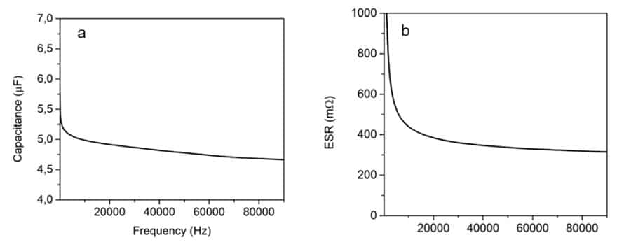
Figure 3 shows a typical capacitance and ESR behavior of the e-cap after fabrication. Frequency dependence of capacitance and ESR data were measured in a range between 20 Hz to 1 MHz, and the values of 1 kHz were used for the comparison between the samples. Figure 3a represents a typical capacitance behavior of the e-caps after fabrication. The observed capacitance for both PEDOT-PSS1 and PEDOT-PSS2 containing e-caps at 1 kHz was ~5.5 µF, where the maximum theoretical capacitance from the standard foil used is 11.7µF for a 20 cm2 projected area. All measured samples showed capacitances within 10% of
5.5 µF except for a single outlier. This indicates that the anode structure is mostly penetrated by the electrolyte. Also, the ESR of the freshly prepared e-caps is stable and constant at ~300mΩ ±30 mΩ (Figure 3b).

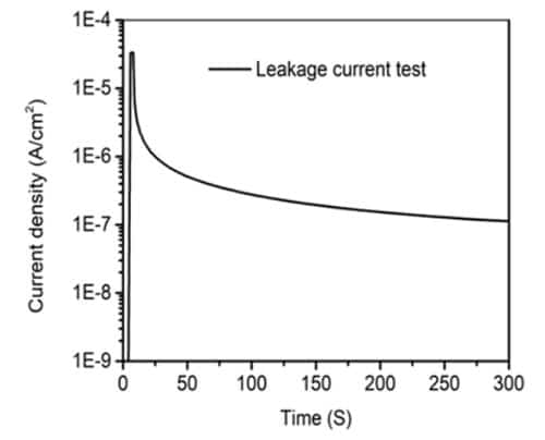
The leakage current of each e-caps was measured to check the status of anodic aluminum oxide as a dielectric. A typical potentiostatic polarization was done with DC voltage of 450V for 5-10 min at room temperature with the current limit of ~1.5 µA per e-cap. Figure 4 represents the current behavior of the e-cap during the long-term aging test. The current increased as a spike at the beginning and stabilized at ~ 5 µA.

The encapsulated e-caps were treated at 105°C at 450V to check their lifetime (aging) test at the high voltage. Capacitance, ESR, and leakage current of the exposed samples were measured before the exposure and in between the aging test.
In the case of e-caps containing PEDOT-PSS1, almost constant capacitance values were observed throughout the long-term aging tests. This indicates that the e-caps with PEDOTPSS1 are very stable at high temperatures (105°C) and high voltages (450 V). Similarly, the ESR was also measured at the same time
interval as the capacitance at 1 kHz just after fabrication and during the aging test. The ESR values at the beginning (after 24 hrs) were slightly unstable but got stable after some time of aging, while the capacitance was almost the same. This might be due to measurement errors, as the rest of the values indicate very little variation throughout the experiment.
The leakage current value after 24-hour exposure to 450 V at 105°C was slightly higher, then decreased to ~ 5 µA after 150 h and became ~ 2 µA after 200 h. This may be indicative of defects in the oxide dielectric being healed by prolonged exposure to the PEDOT: PSS1 at high voltages, which attest to the resilience of the e-caps to high voltage and high temperature over long periods of time. More studies to understand the exact mechanism of this phenomenon are underway.
The lifetime of these e-aps was recorded until ~1800 hours (~75 days). Interestingly, in the case of an e-cap containing PEDOT-PSS2, the lifetime is short compared to PEDOT-PSS1. The recorded lifetime of the e-caps was ~192 hours (~8 days). All parameters, such as capacitance, ESR, and leakage currents,
are not stable and constant throughout the aging tests.
The different PEDOT: PSS contained e-caps that worked perfectly until the last stage of failure. The device failed almost at ~ 1800 h, and the reason for failure was a mechanical disturbance between the anode foil and external connection – revealed by the XRT analysis.
Conclusion
Aluminum-based electrolytic capacitors with polymeric electrolyte, PEDOT: PSS, were successfully tested at 450 V at 105°C for long-term aging tests.
The capacitance, ESR, and leakage current of the successful e-caps were slightly unstable at the beginning but stabilized after some interval of time (~ 1800h) until the failure state. The devices could survive longer with the optimization of the anode connection.
Read the full article here:
S. Neupane, O. E. Olawale, V. Adashkevich, W. Greenbank, L. Tavares and T. Ebel, “Long-term testing results of a high-performance 450 V Polymer Aluminum Electrolytic Capacitor,” 2023 25th European Conference on Power Electronics and Applications (EPE’23 ECCE Europe), Aalborg, Denmark, 2023, pp. 1-6, doi: 10.23919/EPE23ECCEEurope58414.2023.10264312.
References:
[1] J. Schnack, D. Hilper, U. Schümann, R. Eisele, F. Osterwald, H. Beer, and T. Ebel, “Integration Concept for a Traction Inverter with 3D-Printed Embedded Cooling Technology realizing Highest Power Density,” 10th CIPS Int., 2018.
[2] A. Elschner, S. Kirchmeyer, W. Lövenich, U. Merker, and K. Reuter, PEDOT. Taylor & Francis Group, 2011.
[3] A. Shrivastava, M. H. Azarian, and M. Pecht, “Failure of Polymer Aluminum Electrolytic Capacitors Under Elevated Temperature Humidity Environments,” IEEE Transactions on Components, Packaging and Manufacturing Technology, 2017
[4] B-D Steffen, G, Mihaela, E. Thomas, High-Voltage, Low ESR Solid Electrolyte E-Caps for Automotive applications, CIPS 2022.