


This article deals with the issue of assembling conventional SMD components on textile substrates using UV-curable non-conductive adhesives.
The paper was presented by Tomas Blecha, Faculty of Electrical Engineering, University of West Bohemia in Pilsen, Pilsen, Czech Republic at the 4th PCNS 10-14th September 2023, Sønderborg, Denmark as paper No.2.5.
This technology is easily applicable in the textile industry. It thus enables the easy and fast production of e-textiles that are equipped with conventional electronic components or even entire electronic modules.
The article describes the principle of this innovative technology. Furthermore, comprehensive results of testing the effect of mechanical stress, chemical cleaning, and climatic changes on e-textiles with assembled SMD components on the change in contact resistance are presented here. The results show that this technology can be used for assembling and encapsulating SMD components on a textile substrate in the realization of e-textiles.
Introduction
Electronic textiles (e-textiles) consist of electronics and textile parts, where the textile is a supporting substrate for the connection or direct realization of electronic components, e.g., by means of conductive threads or by printing conductive layers. With the help of conductive hybrid threads, some passive components can be realized directly as an integral part of textiles.
We can use standard technologies such as, embroidering or knitting to the creation of electronic circuits and components. Unfortunately, not all electronic components can be implemented in this way, and therefore, when implementing functional e-textiles, it is necessary to use conventional electronic components. The aim is, with regard to user comfort, to permanent assembly these electronic components or possibly entire electronic modules on a textile substrate and connect them to each other based on a suitable technology. Key properties and requirements of e-textile are good flexibility and stretchability, wearing comfort, washability and electrical properties and reliability. In this new part of electronics (it means e-textile) it is possible to find many problematic and unexplored fields of research dealing with a combination of textiles materials and technologies and conventional electronics. One of these fields is standard SMD components contacting the textiles.
Nowadays, three basic options exist for assembling and contacting SMD components on PCBs. Standard technology such as soldering is not compatible with some flexible substrates for electronics and e-textiles. The reason is the high thermal load of not very heat-resistant substrates (PET film, paper, textiles, etc.) during the soldering process. Technology using electrically conductive adhesives do not reach the strength of soldered joints but allows a substantial reduction in thermal load. However, with a reduced curing temperature, the curing time increases significantly, up to several hours. These technologies are therefore completely unsuitable for fast and safe contacting of components on some flexible substrates.
An alternative to the mentioned methods can be non-conductive adhesives, for which very low or even no thermal curing (UV curable polymers) and comparable electrical and mechanical properties of joints with electrically conductive adhesives are sufficient. This contacting technology, as shown by the realized experiments, is particularly suitable for the currently developing field of e-textiles.
Creating an electrical join between an electronic component and conducted pattern based on non-conductive UV curable polymers has several fundamental advantages:
- Almost no heat stress of the substrate.
- Curing of the joint in a matter of seconds.
- Properties of the connection better or comparable to the connections made with conductive adhesives.
- Contacting also creates protection of the component from the external environment (encapsulation).
- Available UV curable adhesives on the market.
- Easy implementation of the technology in industrial production.
The article presents the principle of contacting electronic components directly to conductive pattern realized using conductive hybrid threads on textile substrates. The non-conductive UV curable polymers were used to realize the conductive connection between components and conductive textile ribbons. This type of connection is very easy to realize and can be instantly cured by UV light. The testing of joints reliability is very important and thus testing of the effect of mechanical stress, chemical cleaning, and climatic changes on the contact resistance between the electronic component and the contact surface on the textile substrate was done.
references [1], [2], [3], [4], [5], [6], [7], [8], [9], [10]
MATERIALS AND METHODS
Designed assembly technology consists in applying a UV-curable glue to a textile that contains conductive hybrid threads, then an electronic component is inserted, and under the action of pressure and UV radiation, the glue hardens and thus mechanical and electrical contact occurs between the conductive threads and the electronic elements.
A non-conductive UV curable material is applied to the desired place on the textile, into which an SMD electronic component or flexible printed circuit is inserted under the action of a defined pressure. With this technology, it is possible to contact not only the electronic components themselves but also entire electronic modules. In addition, the encapsulation of an electronic component can be created with the help of UV-curable glue by applying the glue to the component and its surroundings and then curing it with UV radiation. This technology is therefore gentle on textile materials, as there is no contact at high temperatures, such as during the soldering process. Furthermore, this technology is compatible with technologies used in the textile industry.
In order to verify the proposed technology and find possible limitations, a search was made for suitable UV-curable adhesives. The parameters for the search were: UV curable material, secondary curing by heat up to 120 °C, viscosity in the range of 3 – 100 Pa.s and low shrinkage. Based on the research, 3 UV curable adhesives were found and subsequently tested: Loctite AA3926 from Henkel, Vitralit 4732 VT and Vitralit VBB-1 GEL from Panacol.
To verify the functionality and reliability of the contacts realized using UV curable glue, flexible ribbons containing tracks of conductive hybrid threads were used. Each conductive path consists of 5 conductive hybrid threads. Each hybrid thread then contains wires based on Cu/Ag. SMD resistors with a value of 0 Ω and a size of 0603 were glued to these tracks (Fig. 1).

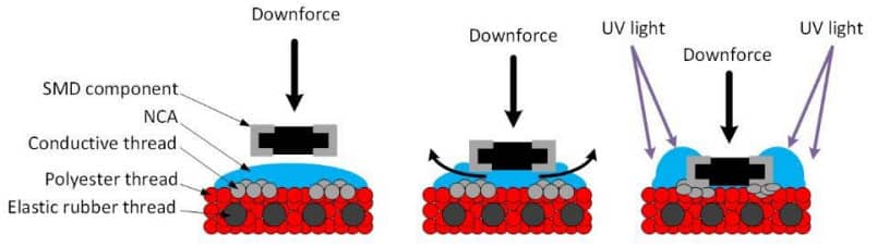
The procedure for contacting SMD components using UV-curable adhesives is shown in Figure 2. In step “S1”, the adhesive was applied on the substrate by pin transfer. In step “S2”, the SMD chip resistors were mounted into the adhesive. In step “S3”, the mechanical pressure was applied onto the chip resistor. In step “S4”, the adhesive was cured by UV light (still with the application of pressure). In step “S5” the resistors were encapsulated by the same adhesive. The electrical resistance was measured by the four-point probe method (step “T1”).


Since 0 Ω resistors were used, the result is the measured contact resistance values between the resistor and the conductive path. The practical implementation of flexible ribbon samples with SMD resistors is shown in Figure 3A, and Figure 3B shows a detail of the contacted resistor on the flexible ribbon. The resistors were subsequently encapsulated (dipped) with UV-curable glue to increase the resistance and reliability of the connection.


To compare the functionality of this technology, samples of flexible ribbons were realized, where SMD resistors were soldered using remelting technology. Bismuth solder paste was applied to the conductive paths of the flexible ribbons using a dispenser, into which an SMD resistor was placed, and then the samples were placed in a remelting furnace for soldering (Fig. 4).


EXPERIMENTS AND RESULTS
Realized test samples were stressed in various ways, such as cyclical stretching, washing and increased temperature when their accelerated ageing occurred. From the obtained results, it can be concluded whether the contacts realized in this way are functional and reliable. For all samples, the electrical resistance between the contacted SMD resistor and the conductive path realized by the conductive hybrid threads was measured continuously. The following graphs show the measured median resistance values for the tested samples. Samples where contacting was done by UV curable bonding are marked as Gxx and samples realized by soldering are marked as Sxx. The second letter in the sample designation indicates whether the SMD resistors were contacted to a ribbon that was in the stretched state (S) or in the unstretched state (N).
Damp heat testing
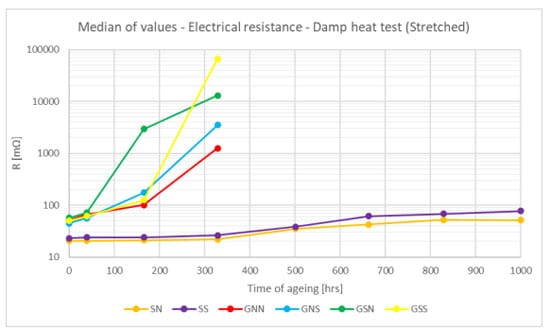
Flexible ribbon samples were tested with moist heat according to IEC 60068-2-2, where this test is intended to simulate accelerated ageing. The samples were tested in the unstretched state and were exposed to a temperature of 85 °C and a humidity of 85% for 1000 hours.
Figure 5 shows the medians of the measured contact resistance values, where it can be seen that already at 150 hours, there is an increase in the contact resistance of the samples made with UV-curable glue. For soldered samples, there is a slight increase at about 500 hours. It is evident from the measured values that the joints made with UV-curable glue are less resistant to increased temperature and humidity. But on the other hand, this test is very “drastic” and it is not expected, taking into account the resistance of textiles, that clothes with integrated electronic elements will be exposed to these increased environmental parameters for a long time.


Washing cycles
Another very important test that was carried out was washing testing. Individual samples were alternately washed and dried according to EN ISO 6330:2012. The entire process consisted of washing at 40 °C, followed by centrifugation at 400 rpm, and finally, the samples were dried at 60 °C or in a hanger. The total number of cycles was 90. After certain washing cycles, the electrical resistance of the contacts was always measured.


The resulting medians of the measured values are shown in Figure 6, where an increase in the contact resistance of the samples realized by gluing after approximately 10 washing cycles is evident. There was no change in the contact resistance of the samples that were realized by soldering.
It is clear from the measured contact resistance values that the biggest changes occur during the first 30-40 cycles. Subsequently, the contact resistance remains approximately constant.
Figure 7 shows the graph of the dependence of the contact resistance (average values, standard deviation, variance) on the number of washing cycles (up to 30 cycles).
Cyclic stretching test
Samples of flexible ribbons with SMD resistors were cyclically stretched to 125 % of their length in the unstretched state, where one stretching cycle lasted 2 s (Fig. 8). A total of 50 000 stretching cycles were performed for flexible ribbons with glued resistors, 28 000 stretching cycles were performed for flexible ribbons with soldered resistors. The contact resistance of the contacts was measured every time after a certain number of stretches. It can be seen from Figure 9 that during cyclic stretching there is no change in the resistance of the contacts for glued but also for soldered resistors.

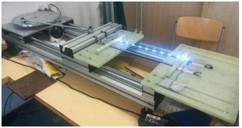


Figure 10 shows a comparison of contact resistances (average values, standard deviation, variance) for samples made with different types of UV-curable adhesives. From the measured values, it can be seen that the best results (smallest change in contact resistance) are achieved with Loctite AA3926 adhesive.


Chemical dry and wet cleaning
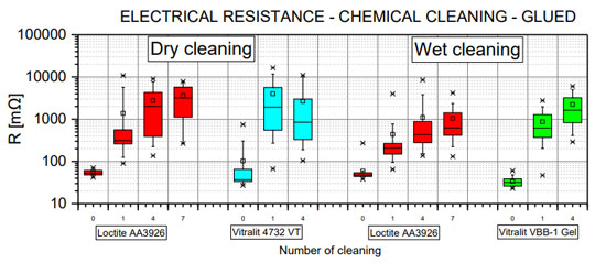
Samples of contacted SMD resistors on conductive ribbons using UV-curable adhesives were subjected to industrial chemical dry and wet cleaning. The parameters of these cleaning processes are shown in Table 1 and they are standard cleaning processes used in dry cleaners. The contact resistance was measured after one and then after three cleaning processes. It is clear from the measured contact resistance values that both chemical and wet cleaning result in a rapid increase in the contact resistance value for all tested adhesives. However, for Loctite AA3926 adhesive, the contact resistance value stabilized around 1 Ω during wet cleaning, see Fig. 11. This value is comparable to the contact resistance value after normal washing cycles. However, with chemical cleaning, there was a significant increase in the contact resistance value of this adhesive. With Vitralit adhesives, there is a significant increase in contact resistance for both chemical and wet cleaning. It is therefore evident from the results that industrial chemical cleaning is definitely not suitable to be applied to contacts made using UV curable adhesives.
| Type of cleaning | Cleaning process temperature | Drying process temperature | Chemical used | Time of cleaning process | Time of drying process |
| Chemical dry cleaning | 30 °C | 60 °C | Tetrachlorethylene | 8 – 15 minutes | 50 minutes |
| Wet cleaning | 25 – 30 °C | 40 °C | Nonionic surfactants; phosphonates, polycarboxylates | 5 – 10 minutes | 30 – 40 minutes |

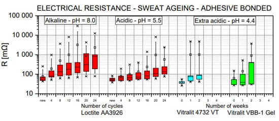
Effect of sweat
As contact between electronic elements and human skin is assumed, the effect of sweat on the contact resistance of the samples was verified. Since sweat can be acidic or alkaline in nature, the samples were exposed to artificial sweat with the appropriate pH. The tests were carried out in parts, where in the first part the samples were immersed for 30 minutes in sweat (acidic/alkaline), then the samples were dried, measured and rinsed for 30 minutes in demineralized water, then they have dried again and measured. Testing was performed in alkaline sweat (pH 8.0) and acidic sweat (pH 5.5) for Loctite AA3926 adhesive. Vitralit adhesives were tested in extra acidic sweat (pH 4.4). Contact resistance values are shown in Figure 12.


SUMMARY AND CONCLUSIONS
From the measured values of the contact resistance of individual joints, depending on the method of stressing, it can be seen that in some cases, especially for joints glued using UV-curable adhesives, the contact resistance increases. A significant increase in contact resistance occurs especially during temperature stress.
The temperature during these tests was 85°C for up to 1000 hours. In fact, textiles with integrated ribbons and electronic elements will not be exposed to such a high temperature for a long time. It can therefore be assumed that there will only be a slight increase in contact resistance, as is the case, for example, with washing cycles. There is a slight increase in contact resistance here, but in the context of the entire electronic system, these values should not affect the resulting function. However, a significant increase in contact resistance was noted in the industrial chemical and wet cleaning tests.
Textiles that will contain electronic elements contacted with a UV-curable adhesive are not recommended for this maintenance method. When comparing individual types of conductive adhesives, Loctite AA3926 has the best properties. In cyclic stretching, which is one of the most important from a practical point of view, there is no change in contact resistance. Based on the results achieved, it can be concluded that the technology of contacting electronic elements using UV-curable textile adhesives is functional and reliable.
Acknowledgement
This research was supported by Technology Agency of the Czech Republic, project no. FW03010095 „MultiTex – Multifunctional smart textiles for improving professional and functional clothing in hazardous environments“ and by the Student Grant Agency of the University of West Bohemia in Pilsen, grant No. SGS-2021-003 “Materials, technologies and diagnostics in electrical engineering”.
References
[1] J. Shi et al., “Smart Textile‐Integrated Microelectronic Systems for Wearable Applications,” Adv. Mater., vol. 1901958, p. 1901958, Jul. 2019.
[2] L. Wang et al., “Application Challenges in Fiber and Textile Electronics,” Adv. Mater., p. 1901971, Jul. 2019.
[3] H. Kim and S. Lee, “Electrical heating properties of various electro-circuit patterns coated on cotton fabric using graphene/polymer composites,” Text. Res. J., vol. 89, no. 19–20, pp. 4114–4130, Oct. 2019.
[4] Y. Wang, S. Gordon, W. Yu, and F. Wang, “Structural architecture of wearable materials based on tri-component elastic-conductive composite yarn: toward a Joule heating application,” Text. Res. J., vol. 89, no. 16, pp. 3303–3311, Aug. 2019.
[5] M. Hirman, J. Navratil, F. Steiner, T. Dzugan, and A. Hamacek, “Alternative technology for SMD components connection by non-conductive adhesive on a flexible substrate,” J. Mater. Sci. Mater. Electron., vol. 30, no. 15, pp. 14214–14223, Aug. 2019.
[6] Hughes‐Riley, T.; Dias, T.; Cork, C. A Historical Review of the Development of Electronic Textiles. Fibers 2018, 6, 34.
[7] Liu S, Tong J, Yang C, et al. Smart E-textile: Resistance properties of conductive knitted fabric – Single pique. Text Res J 2017; 87: 1669–1684.
[8] Lee JC, Liu W, Lo C, et al. Laundering Reliability of Electrically Conductive Fabrics for E-Textile Applications. In: 2019 IEEE 69th Electronic Components and Technology Conference (ECTC). IEEE, pp. 1826–1832.
[9] W. Liu, D. Shangguan, and J. C. Lee, “Evaluation of Launderability of Electrically Conductive Fabrics for E-Textile Applications,” IEEE Trans. Components, Packag. Manuf. Technol., vol. 10, no. 5, pp. 763–769, May 2020.
[10] D. Kalas, S. Suchy, J. Kalcik, J. Reboun, R. Soukup, and A. Hamacek, “Contacting of SMD Components on the Textile Substrates,” in 2020 43rd International Spring Seminar on Electronics Technology (ISSE), 2020, pp. 1–6.