

This article is based on ESA SPCD 2022 paper entitled “EXXELIA New MMLTM Technology for Film Capacitors Miniaturization” written by Tchavdar Doytchinov et. col, Exxelia that was presented during the 4th ESA SPCD conference at ESA ESTEC, The Netherlands 11-14th October 2022. Published under ESA SPCD organisation committee permission.

INTRODUCTION
The trend in electronics is to increase the on-board power, requiring improvements in the energy density of the equipment to limit their size and weight impact. This induces an internal heating and higher ambient temperature for the components and forces designers to improve the thermal management. These trends in power electronics toward ever-increasing miniaturization require smaller and smaller components needing a wide temperature range.
Metallized film capacitors are widely used in power electronics, offering high RMS current filtering and stable characteristics combined with an open-circuit failure mode thanks to their self-healing properties. It remains the compromise with their sizes compared to other technologies (ceramics and electrolytics), which defines the main goal in film capacitor development aiming to reduce size and increase the operating temperature.
The new Miniature Micro-Layer TM (MMLTM) is a breakthrough in film capacitors with an energy density up to 2-3 times superior to the traditional technologies.
This paper describes MMLTM capacitors performance and shows some typical functions that they could address in high-reliability markets. The MMLTM capacitor technology has been licensed to Exxelia by PolyCharge America, Inc. under US patent numbers 9,711,286; 10,102,974; & 10,347,422.
CAPACITORS IN POWER ELECTRONICS FOR SPACE
The main capacitor families used in space applications are tantalum, ceramic and film technologies, each presenting some advantages and weaknesses obliging designers to take technical and economical compromises. Thanks to the porous structure of compressed powders, tantalum capacitors offer small sizes and better energy density for low voltages. Having a dielectric constituted by tantalum oxide, these capacitors are polarized and limited to quite low DC voltages, with very limited capabilities to withstand any reverse voltage.
Having higher dielectric losses and ESR, this capacitor family has limited power capabilities. Tantalum capacitors are widely used for energy storage (backup, lasers, SARadars, etc.) especially in low voltages, presenting a good compromise for integration. Aluminum electrolytic capacitors are another family, which also present very high energy density with a limitation at 630Vdc rated voltage. These capacitors are not typically used in space applications because of lower reliability and their typical degradation and failure mode in storage conditions.
Ceramic capacitors, Type II, cover both low and high voltage applications, offering a good compromise between energy density and better power parameters. The low profile of chip capacitors is appreciated for integration in low power equipment for filtering, decoupling and energy storage. The energy density is obtained thanks to very high dielectric constant, but has limitations due to its high capacitance drift under thermal and electrical field variations. Adding Type I ceramic capacitors, this family is most popular in space electronics, covering lower voltage applications for control and measurement functions, as well as filtering in low power equipment.
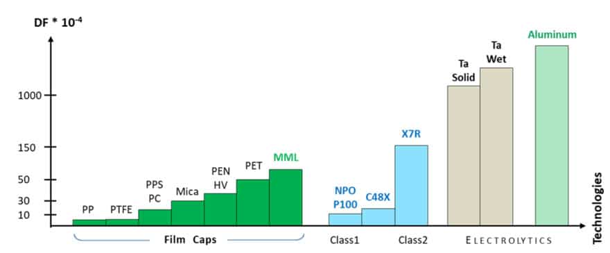
In high capacitance (DC-Link) applications, film capacitor technologies are typically proposed. Having low dielectric constant their sizes are usually large compared to other capacitor families. However, thanks to its low dielectric losses and stable characteristics through a wide range of frequencies and temperature, film capacitors offer an excellent solution in power electronics, showing much better capabilities for RMS and peak currents. Their flexible construction and very light mass translate into excellent thermomechanical performance across a wide temperature range. Different film capacitor technologies are present in ESA, NASA, JAXA and other space systems. Some PP (Polypropylene), PPS (Polyphenylene sulfide) and PET (Polyethylene terephthalate) series are proposed in different systems, but mainly their sizes and shape variants present real difficulties for integration. The power behaviours of different technologies and their dielectric losses could be presented by the comparison of the dissipation factor:

Space is a complex place for passive component providers. Suppliers must not only balance electrical performance, size and weight, when designing products, but also meet a myriad of extremely harsh physical and environmental demands not found in other industries. In the capacitor sector, designing for these considerations often means compromises must be made and, as a result, each dielectric fulfills a niche role.
The introduction of a new dielectric material to the market does not displace another dielectric directly, but instead bridges a gap between existing technologies. Despite the many advantages of metalized polymer film capacitors, these components are often not chosen to populate a board due to their large size. The High-Rel industry is continuously pursuing higher performance in smaller, denser packages which is in turn moving towards boards running hotter. As other components have developed and adapted new high temperature materials and technologies, there is a gap in the market to be filled for polymer film capacitors capable of performing between 125°C and 155°C.
Exxelia’s MMLTM capacitors offer a solution targeting both critical parameters – miniaturization and higher operating temperature.
PARAMETRIC CHARACTERIZATION
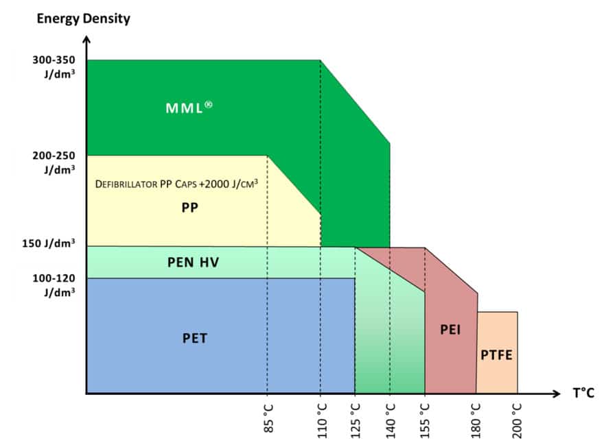
MMLTM capacitors offer a high miniaturization with wide temperature range. The energy density with respect to temperature for this new technology in comparison with some existing polymer film capacitors is shown below:

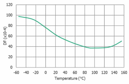
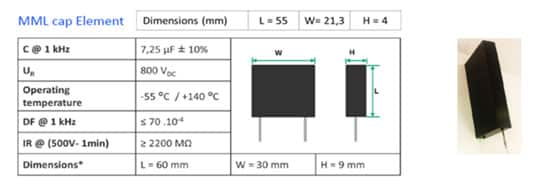
Over the last few years Exxelia performed several tests aiming to evaluate the performances of MMLTM capacitors and characterize their viability for high temperature (>125°C) applications. Some main characteristics of MMLTM capacitor technology with their typical values are shown below in Figure 3. and 4..

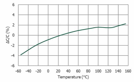

The observed drift in capacitance (Figure 3) is low in the range of -55°C/+155°C with increasing of the value in the high temperature range, which does not present any issue for the power filtering.

Notably, there is a substantial increase in the dissipation factor (Figure 4) from the range of +25°C down to -55°C. Thisis ultimately a self-correcting issue as the higher power dissipation that results would resolve itself through self-heating to a point of equilibrium.
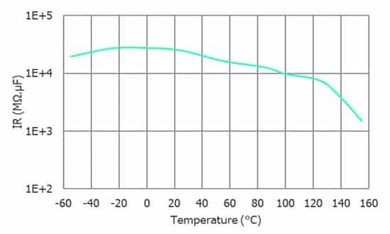
The insulation resistance (Figure 5) also behaves similarly to other polymer film capacitors, dropping off substantially as the temperature increases.
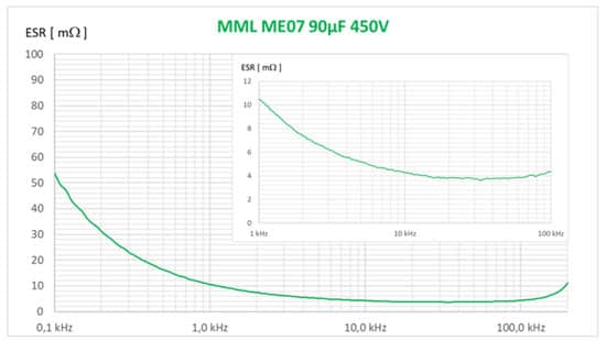
For the frequential characterization different drifts of the capacitance and dissipation factors could be analysed, but the ESR (equivalent series resistance) combines the influences of different parameters and presents the capacitor behaviour for power filtering:
ESR = DF / 2πfC
An example of the frequential response of the ESR for a block capacitor is shown in Figure 6.:

EVALUATION TESTS
The main goal of the technological evaluation is the establishment of the voltage and temperature acceleration factors, but also the failure mode demonstration and EOL (end-of-life) characteristics.
This is a long process based on many data cumulated for different conditions and capacitor values and will be continued in the coming years. This approach is necessary to verify the technological limits and industrial margins. In the technological evaluation approach, several tests have been conducted with different MML capacitor assemblies.
At the same time, Exxelia provided also MML capacitors for some new programs and applications in defense and civil aviation. The capacitors passed with success the rigorous environmental and electrical qualification tests and some of results are included and considered in the more global technological evaluation program. Some factors that influence the capacitor’s ability to withstand the demanding test conditions depend exclusively on packaging, such as mechanical behaviours (shock, vibration, terminal strength) or resistance to humidity, are included in the designing rules.
STEP-STRESS TESTING
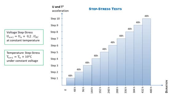
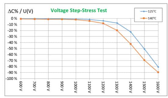
Prior to performing any life testing, several capacitors were subjected to destructive Step-Stress Tests. The Voltage Step-Stress testing was conducted with different capacitors at different constant ambient temperatures. The Temperature Step-Stress testing was performed with different constant applied voltages. Test conditions were maintained during each step (using same duration of 48h or up to 168h) and then the units were cooled to 25°C and retested against baseline characteristics. Units were then returned to Step-Stress conditions at the next step up to failure of 50% of the parts. Below is an example of tests conducted with a moulded single capacitor.


The Voltage Step-Stress tests were performed with a +100V step every 48 hours for 125°C and 140°C ambient temperatures. The results obtained (Figure 8) show a capacitance loss accelerated after 1.6 UR step. Similar degradation of the dissipation factor and insulation resistance was observed. But the test has been conducted up to 2 UR without any short-circuit failure, demonstrating excellent self-healing behaviour.


The Step-stress tests aimed the first investigation of technological margins in voltage and temperature and allowed defining of Steady-state accelerated life tests.
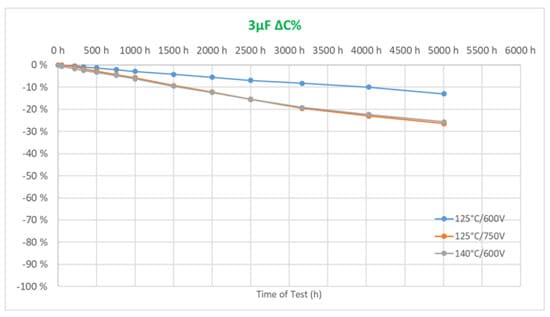
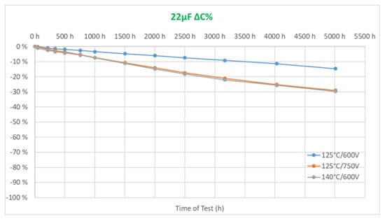
STEADY-STATE ACCELERATED LIFE TESTS
Based on step-stress tests analysis, the conditions for steady-state accelerated life tests have been defined. The life tests results have been analysed in order to define the failure mode in different conditions.


To demonstrate the selfhealing behaviour of MMLTM capacitors, some endurance tests have been conducted outside of the standard drift requirements. An example of test for a 800V rated MML capacitive elements is shown below. This test was aimed at demonstrating the open-circuit failure mode and end-of-life (EOL) characteristics.

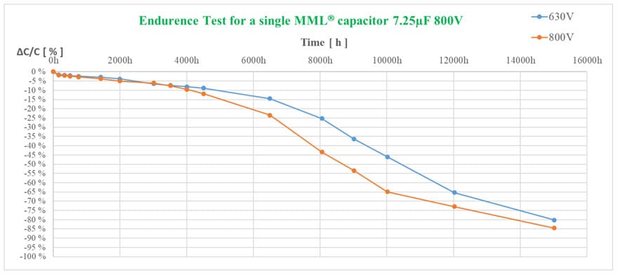
The dissipation factor and other characteristics didn’t show any critical drift. The capacitance drift, without any shortcircuit observation, further demonstrates the self-healing phenomenon and the typical open-circuit failure mode.

POWER BEHAVIOUR AND THERMAL MANAGEMENT
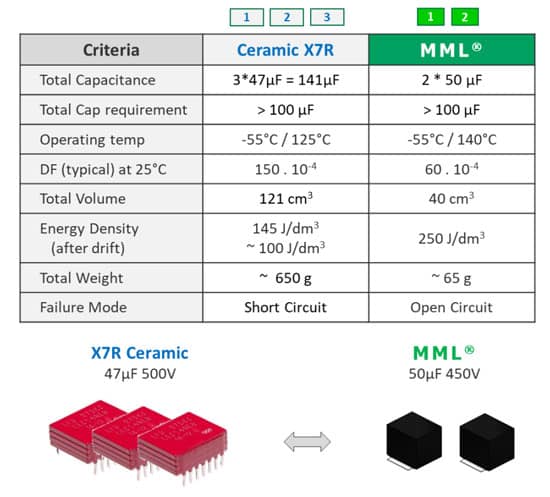
The MMLTM technology is inscribed in the Exxelia Roadmap, but already present in some aerospace and defense projects. These film capacitors allow an excellent downsizing and mass reduction. An easy comparison with ceramic capacitors is presented in Figure 13.
In some high-power filtering, a compromise must be made between size reduction and capacitance value in order to limit the internal heating of the capacitor. Indeed, the size reduction of the MMLTM capacitor has the consequence of decreasing the external surface needed for the thermal exchange.
Keeping a reasonable downsizing and higher capacitance value, which helps for better filtering, could be the compromise for high RMS current filtering.
The internal heating of the MMLTM capacitor, due to the electrical losses combined with relatively small size, is often the main constraint for designers. In some extremal cases the heating estimation in the hot spot must be integrated in the designing taken in account the environmental conditions and integration (Figure 14).


CONCLUSIONS
The results of this study indicate good reliability in performance conditions of MMLTM film capacitor technology as high as 140°C, with opportunities of limited performance capabilities at even higher temperatures. The main challenge to the technology is thermal management of power dissipation, but this can be addressed with high thermal transfer terminations and packaging.
Opportunities for further study include complete characterization of the acceleration factors for determining expected lifetime and MTBF as well as a study of outgassing and radiation resistance of the dielectric.
REFERENCES
- A. Yializis, “Polymeric monolithic capacitor,” US Patent 9,711,286, Jul. 18, 2017
- A. Yializis, “Polymeric monolithic capacitor,” US Patent 10,102,974, Oct. 16, 2018
- A. Yializis, “Polymeric monolithic capacitor,” US Patent 10,347,422, Jul. 9, 2019