by Wai Keung Mo, Kasper M.Paasch and Thomas Ebel
Centre for Industrial Electronics, Mads Clausen Institute, University of Southern Denmark, Denmark
presented by W.K.Mo at the 2nd PCNS 10-13th September 2019, Bucharest, Romania as paper 4.2.
INTRODUCTION
Low Voltage DC Distribution (LVDC) distribution [1] is an innovative method to the public electricity distribution. Because the customers in the LVDC system are supplied with customer-end inverters (CEI), common mode (CM) and EMI noise generated by CEIs must be analyzed. Many previous papers have proposed solutions to EMI reduction such as new modulation techniques, converter topology modifications as well as active and passive filter solutions [2]-[7]. In this paper, the focus is on a novel approach to design passive EMI filters.
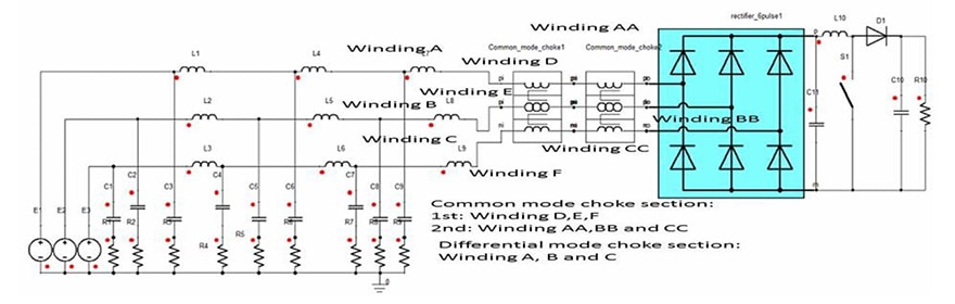
SINGLE PHASE HYBRID MAGNETIC REALIZATION AND SIMULATION RESULT COMPARISON
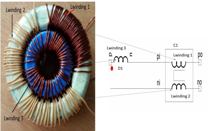
Single-phase hybrid magnetic EMI filter solution is a similar approach as 3-phase solution in next section and Lwinding3 is an inductor winding for differential mode choke, Lwinding1 and Lwinding2 serve as common mode choke windings. To satisfy the safety regulations against electric shock, Lwinding2 must be triple insulation wires as illustrated in Fig. 1. A simple filter configuration is D1 (differential mode choke) and C1 (common mode choke). Lwinding1 and Lwinding2 serve as common mode choke windings.

Comparison simulation results between single-phase standard and hybrid magnetic EMI filter
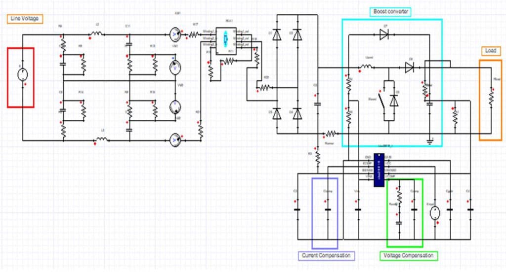
In order to study the behavior of the single-phase hybrid magnetic integrated EMI filter, ANSYS Maxwell and Simplorer were employed [8]. Figure 2 shows the equivalent single-phase boost converter system with 400-ohm resistive load. The simulation test conditions are Vin (E.V) =220V@phase angle=0o.
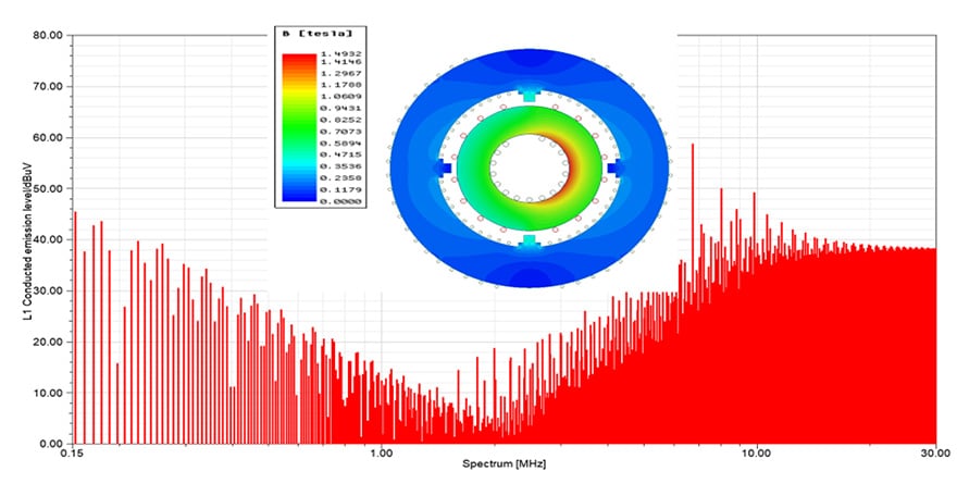
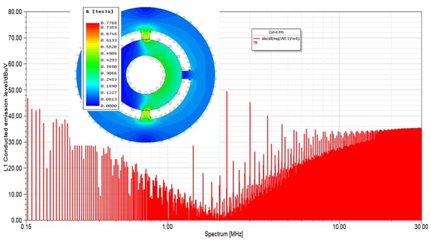
The output power is 368W. Figure 3,4 and 5 illustrate the comparisons of conducted emission levels (L1 line) by the standard and single-phase hybrid magnetic EMI filter solutions. Although both solutions are similar except operation frequency over 6MHz, the hybrid magnetic shows to have less emission around 20dB lower than the standard solution.
This work was supported by Syddansk Vækstforum, the Bitten and Mads Clausen Foundation, the European Regional Development Fund as well as Interreg Deutschland-Danmark with funds from the European Regional Development Fund via the PE: Region project. Find further information on Interreg Deutschland-Denmark on www.interreg5a.eu

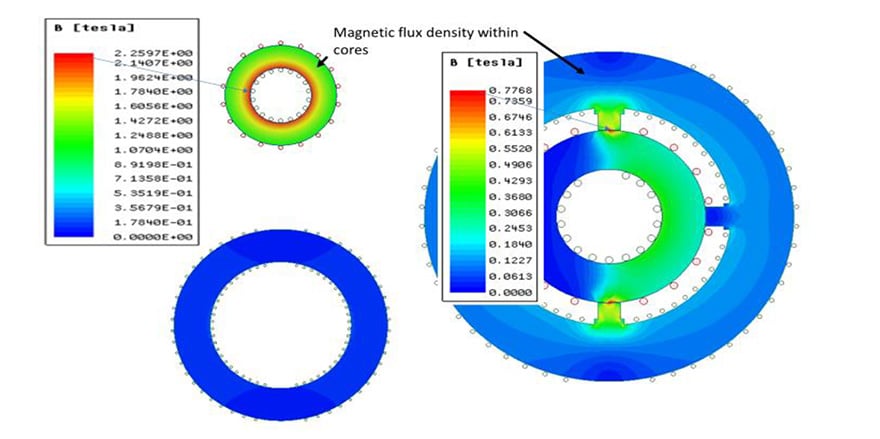
Referring to the benefit of hybrid magnetic solution [9], there is a better balance of magnetic flux density within two cores to prevent the further saturation of magnetic flux density.

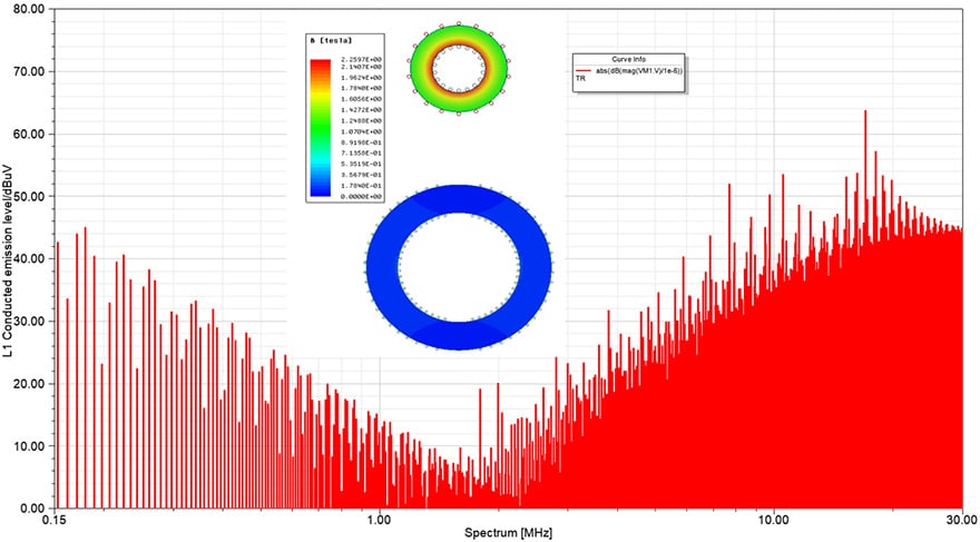
Figure 4 and 5 examine the conducted emission levels under the single-phase hybrid magnetic EMI filter with optimal gap dimension between the inner and outer cores. With appropriate hybrid magnetic EMI filter solution, the magnetic flux density of inner core is below the maximum allowable saturation flux density (≤1.5T) illustrated in Figure 6. However, for the standard EMI solution, the magnetic flux density of the differential mode choke is above its saturation flux density level. It means that the EMI noise attenuation ability of the differential mode choke has gradually faded to result in the largest conducted emission in high operation frequency (f ≥6MHz).


Even though Figure 7 and 8 illustrate that there is no major difference between the standard and single-phase hybrid magnetic EMI filter, the 3th to 15th harmonic orders of hybrid magnetic solution are slightly higher than the standard EMI filter solution.


3-PHASE HYBRIRD MAGNETIC EMI FILTER REALIZATION AND RESULT COMPARISONS
The hybrid magnetic [10]-[11] EMI filter solution is an innovative approach to obtain synergistic effects by merging benefits of different magnetic materials as well as integrated differential and common mode filters. The inner core with low permeability and high saturation level, such as micro-metal Arnold power core-MS series, is appropriate for the differential mode choke.
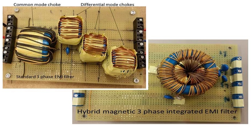
The outer core with high permeability and moderate saturation level serves as the common mode choke. Also, a ferrite barrier serves as a gate to balance the flux density between the inner and outer cores. To satisfy the safety regulations against electric shock [12], all the copper windings should be triple insulation wires as illustrated. Details of the hybrid magnetic 3-phase integrated EMI filter is shown in Figure 9.


3-phase common mode choke section
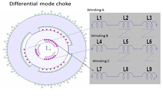
To work as a differential mode choke, the smart solution is to have unequal numbers of copper windings for L1, L2 and L3 power lines as illustrated in Figure 10. Because of the 3 unequal copper turns, the resultant magnetic flux inside the inner core is established progressively to enlarge a differential mode effect in the 3-phase common mode filter construction. Also, this is a major reason for selecting a high saturation flux density core material for the differential mode choke. Figure 11 illustrates the differential mode effect of the inner core because of unbalanced copper turns in Winding A, B and C.


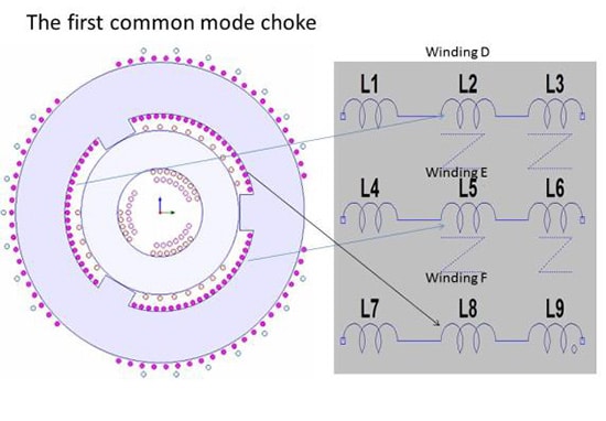
The outer ferrite core is chosen as the 3-phase common mode choke with identical numbers of copper windings shown in Figure 12.


This core was customized with sufficient spaces for copper wires and 5.8mm ferrite barriers between the individual 3 power lines for satisfying the minimum creepage distance requirement [12]. Winding D, E and F (N=22) serve as 3-phase common mode choke windings to provide enough impedance to reduce the common mode noise. However, due to relatively large self-winding capacitance, it only operates in the medium frequency range.
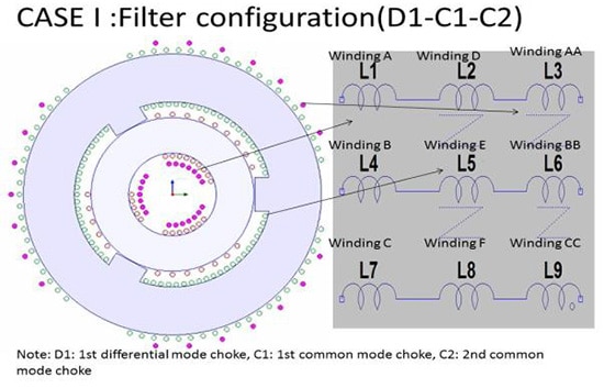
The air gaps between the outer ferrite and the inner powder core work as a gate to balance the magnetic flux between the two cores shown in Figure 11. It means that two cores can work independently because of a large air gap. To have an external high frequency common mode choke, further 3 identical copper windings (AA, BB and CC (N=7)) are put on the top as shown in Figure 13.
Hybrid magnetic solution with different filter configurations
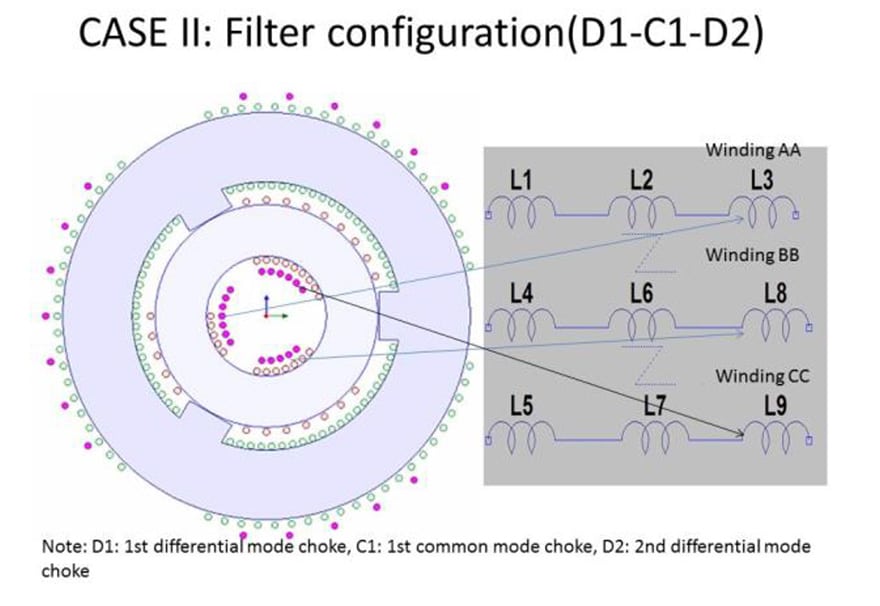
For taking full advantages of the hybrid magnetic properties, the 3 extra-windings are put on the top to establish different filter configurations, either additional common or differential mode chokes. Two instances (CASE I (D1-C1-C2) and II (D1-C1-D2)) are examined in section III. D1 represents the differential mode choke, C1 represents the first common mode choke and C2 represents the second common mode choke.
Optimal filter configurations should be in D1-C1-C2 or D1-C1-C2 as illustrated in Figure 14 and 15, because the D1-C1 filter configuration is not an appropriate solution to reduce efficaciously low frequency differential or high frequency common mode noise. Both types of filter configurations can effectively attenuate the conducted emission from 150kHz to 30MHz.

SIMULATION RESULTS
To study the behavior of the hybrid magnetic 3-phase integrated EMI filter with different filter configurations in section II, ANSYS 2D Maxwell was employed. In the case of unequal numbers of copper turns as shown in Figure 11, the maximum flux density increases progressively to result in a large net magnetic flux within the powder core and an increased differential mode effect. Figure 16 shows the equivalent 3-phase boost converter system with 1000-ohm resistive load [13].

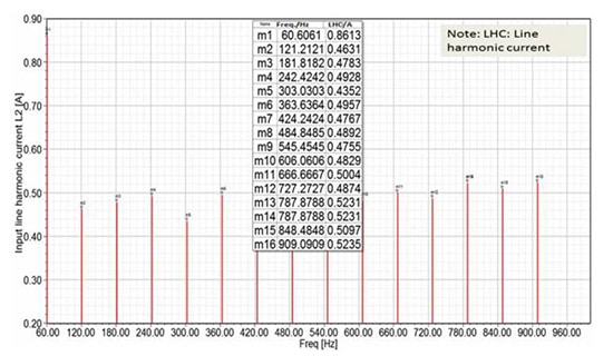
The simulation test conditions are E1=220V@phase angle=0o E2=220V@phase angle=120o and E3=220V@phase angle =240o. The output power across the resistive load is 400W. Input harmonic current contents with different filter configurations for CASE I and II are shown in Figure 18 to 20 and 22 to 24. Finally, the comparison of the simulation result between the standard and the hybrid magnetic integrated 3-phase filter solutions are given in Fig. 25 to 26.
CASE I: D1-C1-C2

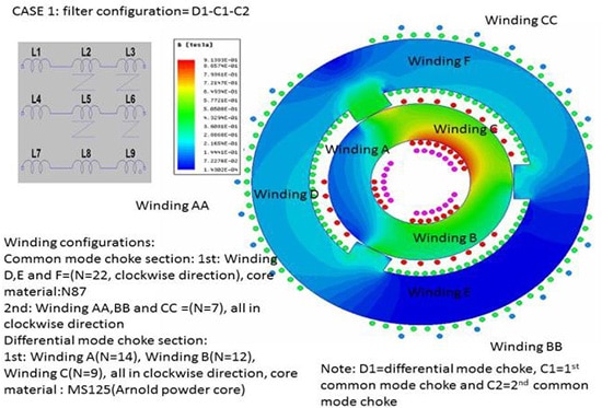

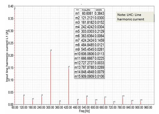
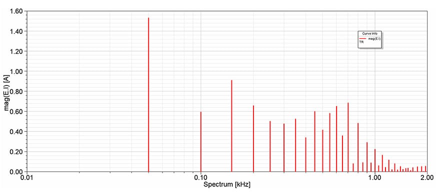
With reference to the section II (filter configurations), CASE I has one differential mode choke and two common mode chokes to connect in series. A detail of CASE I filter and winding configurations is presented in Figure 17. Individual input harmonic current contents of the 3-phase power lines are shown in Figure 18 to 20. The 5th and 7th harmonic order are dominant in the input L1 line harmonic current content as shown in Figure 18. The distribution of all input harmonic currents in L2 and L3 power lines are around 0.5A except 5th (0.62A) and 7th (0.35A) harmonics in the L3 per power line.


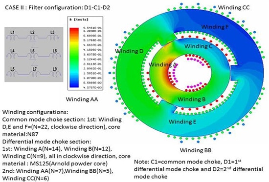
CASE II : D1-C1-D2
Figure 21 illustrates a detail of CASE II (winding and filter configurations). The resultant flux density in the powder and ferrite cores are not the same as CASE I, because it has gradually increased as an increment of the large difference between individual numbers of copper windings in the 3-phase power lines.

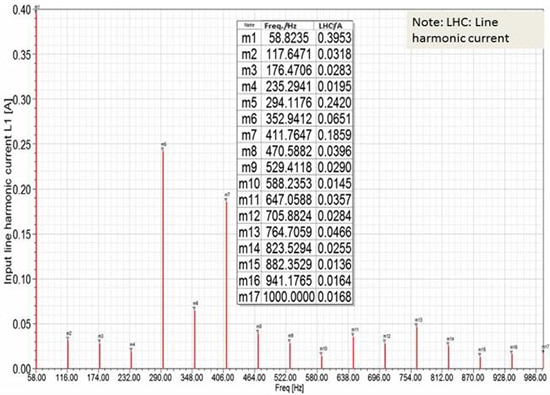
Individual input line harmonic current contents of the 3-phase power lines are shown in Figure 22 to 24.

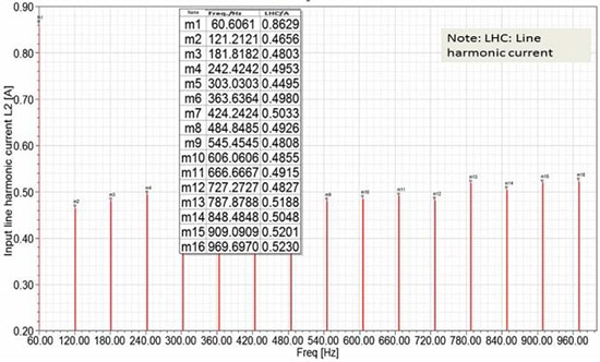

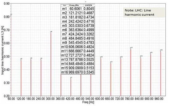
The 5th and 7th harmonic order are dominant in the input L1 line harmonic current content as shown in Figure 22. The distribution of all input harmonic currents in L2 and L3 power lines are around 0.5A except 5th (0.67A) and 7th (0.33A) of harmonic order in the L3 power line.
SIMULATION RESULT COMPARISONS BETWEEN STANDARD AND HYBRID MAGNETIC 3-PHASE FILTER SOLUTION

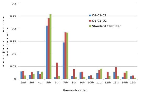

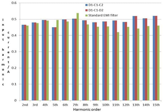
Figure 25 and 26 exemplify input line harmonic current comparisons between the hybrid magnetic solution and the standard EMI filter. Under ANSYS Maxwell 2D analysis, the input harmonic current distribution between the hybrid magnetic and standard EMI filter solutions are comparable for the L2 power line but not for the L1 line as shown in Figure 25. In this figure, the 5th and 7th harmonic order of the hybrid magnetic EMI filter solution in configuration (D1-C1-C2) are 25% lower than the standard EMI filter solution. Furthermore, the D1-C1-C2 filter configuration is better than D1-C1-D2 in terms of input harmonic current content.
LIFE TIME AND MATERIAL COMPATIBILITY
Hybrid magnetic EMI filter contains two magnetic cores with different properties and copper wires with high voltage insulated system such as TEX-E. Although the iron-powder is one of appropriate materials to be used in the differential mode filter section, it suffers from thermal aging because of the eddy current portion of the core loss.
Apart from that ferrite core as a major magnetic core material for the common mode filter section, it can easily crack if it exposed to rapid changes in temperature (thermal shock). There are further investigations should be carried on both issues. However, the short-term solution is to use amorphous core material (no thermal aging effect) such as molypermalloy powder (MPP) instead the iron powder core and nanocrystalline material for the common mode filter section, because it is less thermal expansion in comparison with MnZn ferrite material. Typically, the thermal expansion of nanocrystalline material core is 7.6ppm/deg C and MnZn is 12.5ppm/deg C [14].
EXPERIMENTAL RESULTS

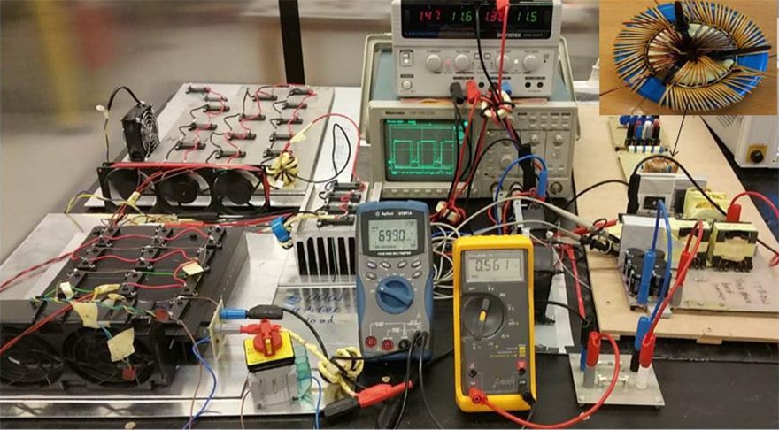
To study the EMI performances of the hybrid magnetic 3-phase integrated EMI filter method, a 400W 3-phase boost converter is constructed with CASE I filter configuration shown in Figure 27. The 3-phase hybrid magnetic integrated and standard filter solutions are presented in Figure 29. Electrical specifications of this converter are given as follow (VNi =220V, fs=10kHz, Vo=700Vdc, Po=400W).

Comparison between 3-phase standard and hybrid magnetic integrated EMI filter

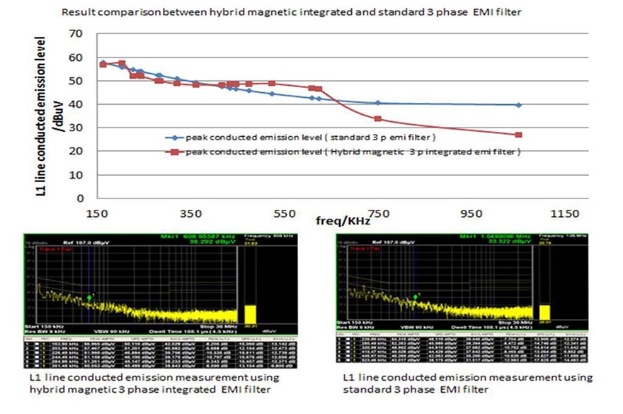
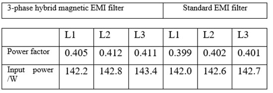
Figure 29 illustrates the L1 line conducted emission levels are comparable for both solutions in the low frequency range from 150 to 350kHz. Although the hybrid magnetic solution shows to have relatively large emission from 350 to 700kHz the conducted emission level is around 10dB lower in the high frequency range. As illustrated in Table 1, the power factor of the hybrid magnetic solution of the 3 individual power lines is larger than the standard filter solution. Also, it confirms the simulation of the input harmonic current content (section III).
Table 1: POWER FACTOR MEASUREMENT COMPARISON

CONCLUSION
The hybrid magnetic single and 3-phase integrated EMI filter are compared to the standard EMI filter. With appropriate winding arrangements and air gap as well as different magnetic properties, it can perform well compared to the standard EMI filter solution.
Furthermore, it is convenient to configure an economically advantageous filter system in terms of different combinations between differential and common mode chokes. The significant advantages are 66% volume reduction and improved power factor in comparison with 3-phase standard EMI filter solution.
REFERENCES
[1] Stephen Whaite, Brandon Grainger, “ Power Quality in DC Power Distribution Systems and micro-grids”, Energies 2015, 4378-4399.
[2] C.Hou, C.Shih, P.Cheng, and A.M.Hava, “ Common-mode voltage reduction pulse width modulation techniques fro three-phase grid connected converters”, IEEE Trams. Power Electron., vol.28, no.4, pp.1971-1979, April 2013.
[3] T.Wang, R.Zhang, J, Sabate, and M.Schutten,” Comprehensive analysis of common mode EMI for three-phase ups system”, in Proc.IPEMC’04, Xi’ an China, Aug. 14-16, 2004
[4] W.Tan, C.Cuellar, “ A common-mode choke using toroid-EQ mixed structure”, IEEE Trans. Power Electron., vol.28, no.1, pp.31-35, Jan 2013.
[5] R.Zhang, X.Wu, “ Analysis of common mode EMI for 3-phase voltage source converters”, In Proc.PESC’03, Acepulco, Mexcio, June 15-19,2003.
[6] D. Dong, X.Zhang, F.Luo,” Common mode EMI noise reduction for grid-interface converter in low-voltage dc distribution system”, in Proc.APEC’12, Vladivostok, Russia, Sep, 8-9, 2012.
[7] R.Lai, Y.Mailet, “ An integrated EMI choke for differential mode noise and common mode noise suppression”, in Proc.APEC’09, Feb 15-19, 2009, pp.2006-2010.
[8] ANSYS Inc,” Getting started with simplorer”, 2012
[9] W.K.Mo, K.M.Paasch, “ Modeling, Simulation and Electromagnetic Conducted Emission Reduction Techniques by Finite element Method”, CPE-POWERENG 2018, Apr. 2018.
[10] W.K.Mo, K.M. Paasch, “Hybrid magnetics and power application”, 2017 11th IEEE international Conference on Compatibility, Power Electronics and Power Engineering CPE-POWERENG, 4-6 April 2017, Cadiz Spain
[11] W.K.Mo, K.M.Paasch, “Hybrid magnetic design”, 2017 IEEE 26th Intenational Symposium on Industrial Electronics(ISIE), 19-21, June, Edinburgh, UK.
[12] IEC,“Adjustable speed electrical power drive systems, safety requirements-electrical, thermal and energy,” IEC 61800-5-1, 2007.
[13] Thomas Friedli,“3D Electromagnetic Modeling of EMI Input Filters”, IEEE Transactions on industrial Electronics, vol.61.
[14] Zsolf Cercsi, “Structural and thermal dependence of soft magnetic properties of FeCo-based nanocrystalline materials”, PhD thesis, Ecole Normale Superieure de Cachan, Cachan, France 2004.
more 2nd PCNS symposium technical papers can be viewed and downloaded in pdf from EPCI Academy e-Proceedings: