

source: KEMET Electronics Corporation; ESA SPCD 2018 Symposium
EPCI e-symposium library article
There is a trend to use the commercial (automotive) grade parts is space applications to reduce the cost of the end electronic device. In Tantalum (Ta) capacitors 50% or higher de-rating (reduced application voltage Vavs. rated voltage Vr) is the way the reliability issues with the commercial parts is addressed. In reality, commercial Ta capacitors with 50% de-rating may be more expensive and less reliable than high reliability or special COTS parts with no/low de-rating, especially, at higher application voltages. Continue to read below.
published by EPCI under approval of ESA SPCD 2018 organizing committee.
Title: Tantalum Capacitors in Space Applications
Author(s): Yuri Freeman and Phil Lessner
Organisation(s): KEMET Electronics Corporation, 2835 KEMET Way, Simpsonville, SC 29681
Symposium: ESA SPCD 2018
Reference: Test, Reliability & Evaluation for space 3.
ISBN: N/A
e-Sessions Applications: Aerospace
e-Sessions Scope Components: Capacitors
e-Sessions Topics: Specification & Qualifications, Technology, Quality & Reliability
Moreover, the testing of the commercial parts by the end-user may be unproductive because the materials and processes in these parts may be changed to reduce the manufacturing cost. In this case the parts from the next production lot may be different from the ones just tested. In contrast to that, changing materials and processes in the Hi-Rel and special COTS parts requires re-qualification and notifying the customers while every production batch is subjected to the established reliability test.
In general, significant amount of data show increased probability of failures and high associated losses due to the usage of the commercial parts in space. According to the NASA Office of Inspector General, since 2009 NASA has suffered four mission failures and one with reduced capability due to the substandard parts [NASA office of audits report No. IG-17-016 from March 29, 2017]. The total agency losses related to these failures approached $1.3B. ESA also reported losses related to the commercial parts [ L. Farhat and D. Lacombe. Lessons learnt at ESA from failures with commercial product/process in space application. Proceedings of the Passive Components Networking Days, Brno, Czech Republic, September 2017].
There is a possibility to achieve the highest reliability and efficiency and potentially reduce the cost of Ta capacitors by using special COTS parts made with advanced flawless technology (F-Tech) and unique simulated breakdown screening (SBDS) and used with no/low de-rating. The thermodynamic foundation and specifics of the F-Tech and SBDS are described in the book Tantalum and Niobium-based capacitors: science, technology, and applications, by Y. Freeman, published by Springer in 2017.
Cited in the book is a comparison of the reliability of the Solid Electrolytic (MnO2) Ta capacitors with F-Tech/SBDS and conventional (Industry Average) technology performed by W. Winkel and E. Rich from the Northrop Grumman Corporation [High Reliability principles and verifications in Solid Tantalum capacitors, Proceedings of the CARTS International 2014]. The experimental values of the failure rate in the baseline D-case 15 uF – 35 V Solid Electrolytic (MnO2) Ta capacitors are shown in Fig. 1.

Fig. 1. The failure rate at rated voltage, 85oC, and 42.25h in baseline D-case 15 uF – 35 V Solid Electrolytic Ta capacitors with conventional (Industry Average) and F-Tech/SBDS technologies
As one can see in the Table, for the same part-type and application conditions failure rate is about 5*107times lower with F-Tech/SBDS vs. the conventional technology. Additionally, de-rating of the F-Tech/SBDS parts provides much steeper reduction in the failure rate (voltage correction factor) vs. that with the conventional technology (Fig. 2).


Fig. 2. Failure rate voltage correction factor in D-case 15 uF – 35 V Solid Electrolytic Ta capacitors with conventional (Industry Average) and F-Tech/SBDS technologies.
According to Fig. 2, 20% de-rating of the KEMET F-Tech/SBDS parts provides more reduction in the failure rate then 50% de-rating of the Industry Average parts with conventional technology. In both cases the experimental data fit well power function; however, the exponent in this function is about 4x larger with F-Tech/SBDS vs. the conventional technology resulting in the steep drop in the failure rate with the de-rating.
Shown in Fig. 1 and 2 experimental values of the failure rate in the MnO2Ta capacitors were obtained via step stress life test (SSLT) with gradual increase of the applied voltage above the rated voltage and hold time at every step. Similar SSLT test was performed on the same type D-case 15 uF – 35 Polymer Ta capacitors manufactured with F-Tech/SBDS. The materials and processes in Polymer capacitors were the same as these in MnO2capacitors except the cathode where manganese dioxide was replaced with the conductive polymer. The polymer technology was either hybrid with internal in-situ polymerization and external pre-polymerized slurry or special slurry internally and externally (the book, chapter 2.3). Fig. 3 shows the SSLT results for the D-case 15 uF – 35 V MnO2, Polymer Hybrid, and Polymer Slurry capacitors.


Fig. 3. SSLT results for the D-case 15 uF – 35 V Ta capacitors with F-Tech/SBDS and different cathodes
As one can see in Fig. 3, no Polymer capacitors failed at the test conditions that induced the failures in practically all the MnO2capacitors. These results demonstrate exceptional strength of the dielectric in the Polymer Ta capacitors manufactured with F-Tech and SBDS. This exceptional dielectric strength was also confirmed by the BDV test (Fig. 4)
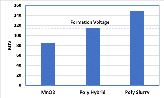

Fig. 4. BDV in the D-case 15 uF – 35 V Ta capacitors with F-Tech/SBDS and different cathodes
Fig. 4 shows that a combination of the advanced anode and dielectric technology (F-Tech), special slurry polymer technology, and unique screening technique (SBDS) provides the highest dielectric strength, and, thereby, stability and reliability, ever achieved in any Solid Ta capacitors.These Polymer Ta capacitors also demonstrate the highest application voltage and lowest DCL, which are comparable to these in Wet Ta capacitors, while their ESR is much lower than ESR in Wets. As an example, Fig. 5 demonstrates evolution of the B-case leaded Ta capacitors
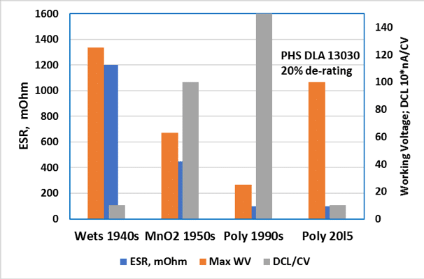

Fig.5 Evolution of Ta capacitors
The major moving force for the evolution of Ta capacitors is reducing ESR to allow higher operating frequencies and lower heat generation by the ac current. During half a century progress in ESR was accompanied by reducing the operating voltages and increasing DCL first in Solid Electrolytic (MnO2) and then Polymer Ta capacitors. When Polymer Ta capacitors were developed in 1990s, they were low voltage, leaky and unreliable; though, their ESR was significantly lower vs. ESR in Wets and MnO2Ta capacitors.
Shown in Fig. 5 Polymer 2015 Ta capacitors present KEMET Polymer hermetic seal (PHS) Ta capacitors manufactured with F-Tech/SBDS, special polymer slurry, and controlled amount of humidity in the hermetic can (the book, chapter 3.3). These Polymer Ta capacitors have working voltage and DCL similar to these in Wet Ta capacitors while much lower ESR, especially, at low temperatures. The PHS are covered by the DLA 13030 and have been successfully used in space for about five years.
With any technology, the de-rating has stronger impact on the volume and weight of Ta capacitors in comparison to the other types of the capacitors. For instance, 50% de-rating of the ceramic capacitors typically results in approximately 2x volume increase to maintain the same capacitance.
In contrast to that, 50% de-rating of Ta capacitors results in about 10x increase in volume and proportional increase in weight to maintain the same capacitance. The strong impact of the de-rating on the volume and weight of Ta capacitors is due to the combination of the thicker dielectric and coarser Ta powder with lower specific surface area needed to form the thicker dielectric on the Ta anodes.
As an example, Fig. 6 shows Solid Electrolytic Ta capacitors with capacitance 4.7 uF and application voltage 25 V: D-case 4.7 uF – 50 V (50% de-rating), B-case 4.7 uF – 35 V (30% derating), and A-case 4.7 uF -25 (no de-rating). The ratio in volume and weight in these capacitors is approximately 10:2.5:1.
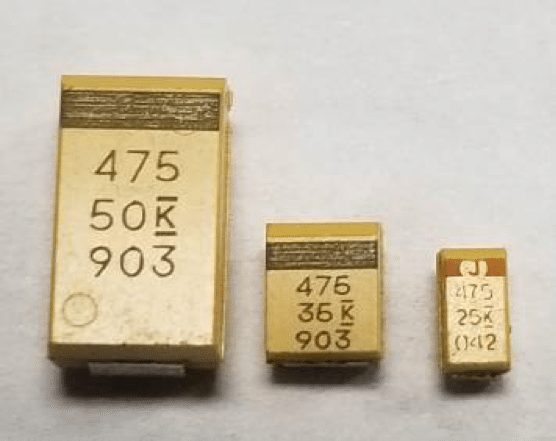

Fig. 6. Surface mount Solid Electrolytic Ta capacitors D-case 4.7 uF -50 V, B-case 4.7 uF – 35 V and A-case 4.7 uF – 25 V
The increase in volume of Ta capacitors due to the de-rating means equal loss in the volumetric efficiency in terms of charge (CV/cc) and energy (E/cc). At the same time, the high volumetric efficiency is the major advantage of Ta capacitors in comparison to the other types of the capacitors.
The 10x loss in volumetric efficiency due to the 50% de-rating makes efficiency of Ta capacitors comparable to that in less expensive ceramic capacitors. Besides that, thick dielectric in the higher voltage Ta capacitors made with conventional technology and used with 50% de-rating contains large number of the initial defects that can progress and cause the field failures even with the de-rating.
In this case the de-rating has negative effect on the reliability. Finally, the 10x increase in volume due to the 50% de-rating and proportional increase in weight result in higher manufacturing cost, which depends strongly on the amount of Ta powder in Ta anodes.
Though F-Tech and SBDS add to the manufacturing cost, Ta capacitors made with the F-Tech/SBDS and used with no or low (20%-30%) de-rating provide not only higher reliability and efficiency, but potentially lower cost in comparison to the larger size commercial Ta capacitors used with 50% de-rating.
The F-Tech and SBDS also help reduce anomalous charge current (ACC) in higher voltage Polymer Tantalum capacitors (the book, chapter 3.5). As an example, Fig. 7 shows the current at V = 28 V during the ramp test (dV/dt = 120 V/s) of the non-hermetic D-case Polymer Ta capacitor 15 uF – 35 V manufactured with conventional (a) and F-Tech/SBDS (b) technologies. Before the ramp test the capacitors were bake-out at 125oC and then cooled down to 0oC.
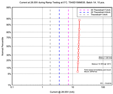
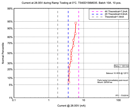


Fig. 7. Ramp test of the 540D Polymer Tantalum capacitors 15 uF – 35 V manufactured with conventional technology (a) and F-Tech/SBDS (b)
As one can see in Fig. 7, the current values are lower with F-Tech/SBDS vs. conventional technology, though, still higher than theoretical current value calculated as I = C*dV/dt. The work is in progress to reduce the current to the theoretical level (eliminate ACC).
Conclusions and Recommendations
- Only Hi-Rel and special COTS Ta capacitors with established reliability are recommended for the space application.
- Commonly used 50% de-rating of Ta capacitors results in 10x increase in volume and proportional increase in weight and cost. It can also have negative effect on the reliability of the higher voltage Ta capacitors made with conventional technology.
- Ta capacitors made with F-Tech/SBDS and used with no or low (20%-30%) de-rating provide high reliability and efficiency as well as potentially cost benefits vs. larger size Ta capacitors made with the conventional technology and used with 50% or higher de-rating.
- Polymer Ta capacitors made with F-Tech/SBDS and special polymer technology provide not only low ESR, but also the highest dielectric strength, and, thereby, stability and reliability, ever achieved in any Solid Ta capacitors.
- The F-Tech and SBDS help suppress ACC in higher voltage Polymer Ta capacitors combined with high stability and reliability.
Acknowledgement:
The authors would like to acknowledge important contributions to the experimental part of the work and very helpful discussion by Bill Winkel, Ed Jones, Erin Atkinson, Steve Hussey, Jonathan Paulsen, and Jimmy Cisson.
read the full technical paper in pdf here:
![]()

and presentation here:
![]()