


")


This paper offers a study of modern capacitor performance in energy harvesting of ULP ultra-low power and energy harvestor sources.
The paper was presented by Ron Demcko and Slavomir Pala, KYOCERA AVX at the 4th PCNS 10-14th September 2023, Sønderborg, Denmark as paper No. 5.2.
Abstract
Semiconductor advances have brought about opportunities to power electronics in highly novel and efficient ways. An extreme example is the ability to power Ultra Low Power ICs with a combination of a Tantalum capacitor (wake up power) and a supercapacitor (for processing power). ULP ICs draw such low amounts of power (100nA storage mode, 500nA standby, 1uA – RTC mode) that energy harvesting/scavenging means are adequate to create set and forget circuits with virtually zero maintenance. This is very attractive since maintenance costs and battery waste can be virtually eliminated.
This study will look at energy harvesting ULP power sources and outline capacitor performance & trends for each end use.
Ultra-Low Power ICs
Semiconductor manufacturers have sizeable programs to develop and produce reduced power demand ICs since the market for Ultra Low Power (ULP) actives is projected to grow to 70% of total microcontroller units (MCU) shipped in 2027.
The potential market demand for ULPs is staggering with the IoT sector alone projected to demand approximately 31 billion MCUs by 2025 alone. Industrial, wearables and medical sectors also are providing notable demand for ULPs. [1]
Microcontrollers are essential to all those sectors and applications since they enable the applications viability. However, MCUs must reduce power to improve longer battery life. Consider the productivity gains of 16.7 billion IoT devices currently in place in the 2023-time frame with a projected growth to over 29 billion devices in 2027. [2] It is not practical or possible that batteries on these devices can always be changed. Batteries must be made to last longer or be eliminated totally in order to manage labor costs, reduce the potential to damage the IoT device during battery swap out and reduce or eliminate the waste from dead batteries.
Though many methods are used in power reduction efforts, ULP semiconductors are typically created through combinations of reduced die size, lower operating voltage rails, special processing techniques/designs, selectable timing sources & reduced clock rates. End use factors such as end product use temperatures, duty cycles/software factors (wake up times to processing complexity & duration – etc.) and added periphery circuitry affect battery life.
ULP Definition
The expectations of what defines ULP changes with time but one past graph best represents a high level snapshot of ULP Performance and its limitations relative to power sources. See Figure 1 – ULP MCU practicality by power source defined by standby current, active current (uA/ MHz) and line geometry.
This graph shows multiple manufacturers approach to ULP MCUs as gray dots which are grouped into 3 general clusters (oval areas) based upon line width geometry. Those line width groups are then plotted against standby current and active current (normalized in terms of uA/MHz).
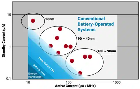
This graph provides a high-level view on the types of power sources Ultra Low Power ICs can be powered by. [3] As the required current draw from the IC reduces in magnitude, its power demands are also reduced assuming similar software & use duty cycles. This graph illustrates the fact that ULP power requirements have dropped to such a low level that energy harvesting can be used to replace batteries and thereby create a set and forget MCU based systems.
Impact of Active to Standby Ratio
The partitioning of ULP MCU characteristics by standby to active currents is important since the ratio of active to standby mode defines the average power of the ULP MCU. See Figure 2.
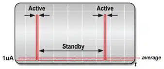
An example of average power limiting battery life follows where battery life expectations of a common MCU with a 1% and 0.1% active mode ratios are investigated.
A 1% active period translates to 14.4 minutes of active time / day. An example of a device using this type of duty cycle might be a data measurement sysyem for air quality or a medical monitoring device. [4]
In the 1% active period example, the total average current is the sum of standby power consumption and active power consumption. Or 0.99 x standby power consumption and 0.01 x active power consumption.
A real world example can be shown with a Texas Instruments M430F26xx MCU powered with a low leakage CR2032. The standby current for this MCU is 0.6uA and active current is 515uA.
This example translates into:
- M430F26xx = 0.6µA × 0.99 + 515µA × 0.01, 200mAh/0.0058mA/24/365 = 4.0 years
Changing the same MCU active to standby ratio to 0.1% and still powering the MCU with a CR2032 will greatly effect the battery life of the syste. Calculations for this use case follows.
- M430F26xx = (0.6µA × 0.999)+(515µA × 0.001), 200mAh/0.011/24/365 = 21 years
Of course 1% and 0.1% active to standby ratios may not be practical in end customers systems because of the task at hand. Sampling rates and active regions could very well eat up battery life so much that the MCU may exhibit much less than 4 years of battery life.
Therefore energy harvested power can be a very attractive alternate to achieve maintenance free ‘set & forget‘ performance.
Set & Forget ULP MCUs
Several ULP MCUs were available for testing but a Renesas RE01 was chosen due to its simple implementation and evaluation board availability. This MCU has an Energy Harvesting Controller (EHC). The EHC accepts energy generated from solar, piezo, Thermal Electric Generators (TEGs), pressure – etc. It then manages harvested power by channeling and balancing energy through one of the two capacitors to powering the MCU. To achieve this, the EHC contains sub-level PMIC, charge controller, and power management functionality.
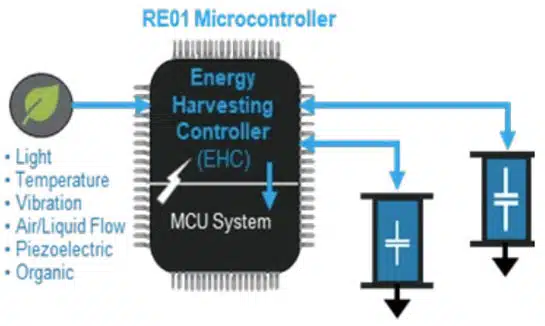
On a more functional basis, the EHC can be viewed in many ways. It provides functions as basic as reverse current protection. However, it provides more complex functionality when viewed as the direct energy-harvesting link—controlling voltage regulation, quick start-up control, autonomous and reliable start-up sequencing, start-up current control, energy storage charge management selection of capacitor power sources. The configuration of an energy powered RE01 MCU is shown in Figure 3.
In this example, temporary energy storage is provided by a tantalum capacitor and secondary storage is provided by much larger capacitance value super capacitor. As previously mentioned, when the RE01 MCU is configured to operate from an energy harvesting power source, the EHC relies upon a start-up capacitor, C-SU, to charge quickly and provide the low-level power for MCU power up initiation. Long-term power comes from batteries (or in the case of this study – supercapacitors).
Start-Up Capacitor Requirements and Options
The start-up capacitor C-SU is required to:
- Operate from -40°C to + 85°C
- Provide 100 to 150µF of capacitance across temperature
- Exhibit Low ESR due to charge currents from various charge sources
- Exhibit low leakage current (high insulation resistance) to reduce standby currents
- Use little board area
- Have the ability to be processed with standard PCB processing & operate reliabily
There are three capacitor technology options available for a 100 to 150µF storage capacitor used at ~ 3V. A comparison of Tantalum, Aluminum Electrolytic and Multi-Layer Ceramic Capacitor (MLCC) technologies is shown in table 1. This table shows that Tantalum capacitor technology meets the requirements of a start-up charge retention capacitor. Tantalum capacitors offer significant advantages over high CV MLCCs as well as Aluminum electrolytic capacitors.
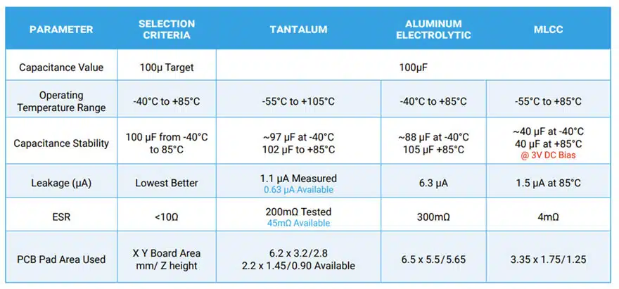
A Tantalum capacitor, Kyocera-AVX P/N: TPSC107K010R0200 was chosen as the start up capacitor since they do not exhibit capacitance instability due to DC bias, operating temperature, or age. Capacitance instability is a major disadvantage for MLCCs since a 100µF rated part may actually demonstrate 20 or 30 µF properties while biased in application. Capacitance instability plus large physical size are the main reasons that MLCCs are not recommended for use as start-up capacitors. Aluminum Electrolytics offer more stability than MLCCs, but that comes at a price of increased size, weight, and potentially much less reliability. Although Aluminum Electrolytic capacitors exhibit large capacitance values in small case sizes their electrical properties vary with temperature.
The TPSC107K010R0200 has AEC Q200 automotive grade qualification and is available in 14 different case sizes with voltage ratings from 2.5 to 50V and values from 0.15 µF to 1500 µF.
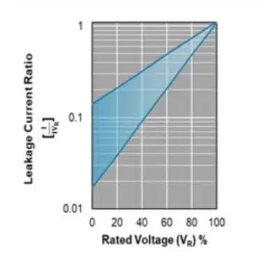
Options exist for designers to further reduce the in-circuit leakage by derating the capacitors’ voltage rating. [5]
A graph depicting the extent to which leakage currents reduce from derating is shown in Figure 4.
Bulk Capacitor Requirements and Options
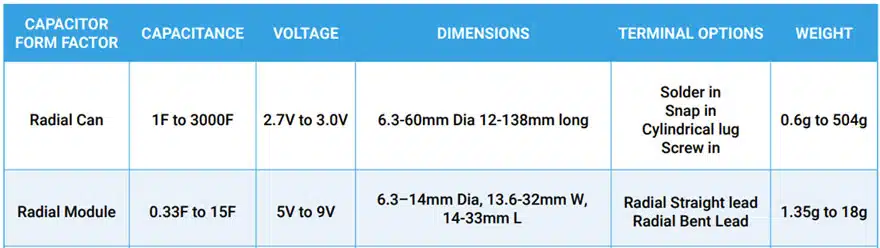
Supercapacitors are generally recognized as a low cost alternative to a rechargeable battery when hundreds of thousands to ~ million charge/ discharge cycles are needed. Supercapacitors multiple form factors contribute to the ease of implementation in end systems. Multiple options exist for supercapacitor selection (see table 2 comparison) and the end device selected depends upon the desired applications run time and package characteristics of the supercapacitor.
Radial Can Discrete Supercapacitors
Ultra-miniature Supercapacitors offer designers maximum flexibility through:
- Multiple product series available
- Multiple voltage offerings
- Ten different case sizes
- Highest number of capacitance values available
Radial can parts are commonly used in single configuration for lower voltage designs or multiple cans can be configured to obtain the correct voltage/energy for higher voltage loads. Multiple cans can be balanced via active or passive methods. Supercapacitor balancing is needed to ensure long life for multiple supercapacitors used in series. Balancing each Supercapacitor prevents damage from over-voltage to other Supercapacitors in the stack. Since passive balancing is accomplished with a resistor, it has the advantage of being the cheapest, smallest, and easiest to use. However, the big disadvantage from passive balancing is that power is dissipated through the balancing resistor, which reduces efficiency. Active semiconductor balancing is the most efficient and exacting method. However, its costs are more significant. The size required for active balance solutions varies greatly based upon the number of cells in need of balancing as well as the size of cell/semiconductor type’s used in balancing.
Radial Modular Package Supercapacitors
Aluminum Radial modular packages are manufactured by connecting two radial can aluminum capacitors in series and packaging them into a ‘module’. These packages offer maximum efficiency of package density and a higher rated voltage than single can Supercapacitors. Applications with higher voltage batteries often find these packages very beneficial for simplifying design. As discussed previously, radial modules can be balanced or unbalanced and have the options for hard-shell or heat-shrink packaging depending upon the end user’s need for enhanced reliability.
SuperCapacitor Parameters
Three of the most important electrical characteristics of supercapacitors are:
- Capacitance
- ESR
- Leakage Current
The capacitance of a supercapacitor is stable from 0°C to 40°C [approximately -10%]. Since capacitance values are very large ~3 Farads/ cc, capacitance drop can be substantial. Due to this, capacitance-temperature effects are more of a reliability concern, opposed to a minor drop in capacitance. The lifetime of a supercapacitor is extended an order of magnitude for every 10°C reduction in operating temperature, as mentioned previously. The ESR of supercapacitors can be exceptionally low (single digit milliohm values) based upon capacitance value and case size of the selected device. ESR values increase with decreasing temperature. At 0°C, values are typically 125% of the 25°C value and increase to ~ 225% at ~ -40°C. Leakage currents also vary by capacitance value, voltage rating, packaging style and temperature. Temperature effects impact leakage by decreasing the 45°C value to near zero at ~-40°C and increasing to ~650% of the 45°C value at ~85°C. Generally speaking the supercapacitors performance at temperature extremes greatly eclipses that of a battery over the medium to long haul. Supercapacitor voltage ratings are commonly ~2.7V per cell. They can be stacked in series to create higher voltage operating stacks. The end user can perform stacking or small stacked modules of all sizes that are available from manufacturers. The wide availability of power management ICs with cell balancing tends to dictate the economics of single cells configured by end users.
Test Results
The RE01 ULP MCU was connected to a small 1-watt solar panel to show the charge / processing times available during a case based upon energy scavenging and operation.
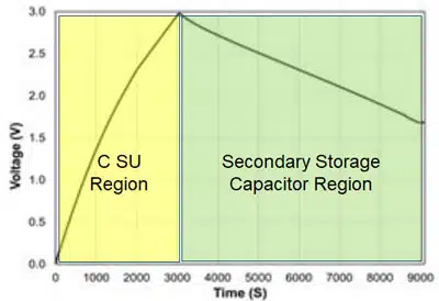
The results of this test show a 1 Farad bulk capacitor charge time to be ~ 20 minutes to the point of useful processing and wake up voltage.
It should be noted that during this period the start-up tantalum capacitor was powering the MCU to perform low level sleep & wake up transition monitoring.
The device continues to charge – though at a slightly presence due to varying active cycles used in the RE01 self-check. Once the maximum EHC voltage of 3volts was attained, the solar panel was disconnected to illustrate a worst-case use duration of a charged 1 Farad ‘C bulk capacitor’.
The period of useful processing time was ~130 minutes based upon the internal active-standby cycles of the RE01 performing an infinite loop of self-check instructions. See Figure 5.
SUMMARY AND CONCLUSIONS
The trend of ULP ICs will continue and potentially accelerate as IoT and portable electronics proliferate. Corporate Green policies will recognize the attractiveness of battery waste and cost advantages associated with zero maintenance and the elimination of damaged IoT modules as a result of battery maintenance.
Though absolute power ratings are affected greatly by software demands dictated by end use requirements of the ULP, successful energy scavenged powering was proven to be possible – even when an MCU is put into self-check modes.
Tantalum capacitors exhibit stability, reliability and size advantages recognised as attractive and enabling to the role of start-up capacitors. Options exist for bulk capacitors to address the various packaging and power needs associated with broad sizes and tasked MCU based systems.
REFERENCES
[1] ( Omar Mohammed ); Ultra-Low-Power Chips Expedite Energy-Efficient Designs; Electronic Design; August 31, 2022 Ultra-Low-Power Chips Expedite Energy-Efficient Designs | Electronic Design‘
[2] (IoT Analytics); IoT connections market update – May 2023,
[3] (Ken Imai); Renesas Electronica America Inc; 7-24-2020; SOTBTM MCU BASED ULTRA-LOW POWER AIR QUALITY MONITORING SOLUTION
[4] (Tech Brief, Zack Albus, Adrian Valenzuela, Mark Buccini – 2019) TEXAS INSTRUMENTS white paper; Ultra-low Power Comparison: MSP430F2x MCUs vs. Microchip XLP
[5] KAVX Polymer, Tantalum and Niobium Oxide Capacitor Catalog; 2023; Kyocera-avx.com


