


")


Power FLEX transformers
The FLEX transformers (Figure 2.86) are especially well suited for DC-DC converters in the lower power rang. As a result of their winding structure, consisting of six individual windings each with the same number of turns, as well as the various air gaps available, the Flex transformers are very flexible in their application. Table 2.38 shows the different sizes, and Table 2.39 the most important electrical parameters.
![]()
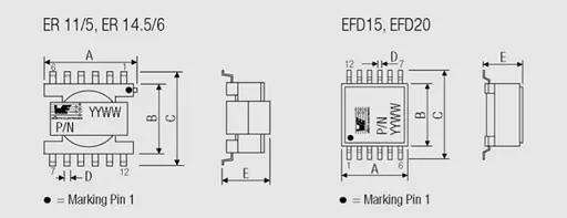
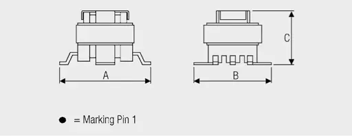
Tab. 2.38: Mechanical dimensions of the FLEX transformers
![]()
Fig. 2.86: FLEX transformers for switch mode power supplies
![]()
Fig. 2.87: Schematic representation of the FLEX transformers
The appropriate connections wiring of the windings on the circuit board allows various inductance and transformers with different turns ratios to be generated (Figure 2.88).
![]()
Fig. 2.88: The use of a Flex transformer with a turns ratio 1 : 3 with layout recommendations
When calculating the resulting currents and inductance, it must be kept in mind that the six windings are wound on the same core – so they are magnetically coupled. Connecting two discrete inductance in series, the inductance are added (Equation 2.57). Connected in parallel, the reciprocal values of the inductance add together (Equation 2.58), i.e. connecting two equal inductance in parallel produces half the inductance.
![]()
Fig. 2.89: Parallel and series connection of the WE-FLEX transformers


Connecting windings to a common core means adding the number of turns. These are squared in the calculation of the resulting inductance. As the number of turns of the single windings for WE-FLEX is identical, the resulting inductance is proportional to the square of the number of windings connected in series (Equation 2.59).

For parallel connection, the number of turns stays the same; only the conductor cross-section changes. So with parallel connection there is no change in inductance (Equation 2.60).

Lbase inductance of a winding
To determine Isatbase all six windings were connected in parallel and the inductance measured as a function of current. The saturation current determined in this way is the total saturation current of the component. Isatbase is then the measured saturation current divided by six.

Consequently, the total saturation current of the transformer is six times Isatbase. This total saturation current can now be distributed over the current-carrying windings. If, for example, three windings are connected in series, the six times Isatbase can be distributed over these three windings. Hence, each of these windings may carry current of twice Isatbase.
In the case of parallel connection of three windings, these can also carry twice Isatbase. For parallel connection, the individual currents add together to produce the total current, six times Isatbase. The following rules generally apply:


nI number of current-carrying windings
In contrast, the rated current, which is a property of the wire diameter, cannot be distributed to other windings. The resulting rated current for series and parallel connections is given by the following formulas:


The saturation current is not crucial when it comes to dimensioning transformers as forward converters or push-pull converters, but rather the voltage-µs product. Table 2.39 on page 266f specifies the voltage-µs product for a winding. The voltage-µs product or Volt-µs product is proportional to the number of turns, so that the Volt-µs product from Table 2.39 has to be multiplied by the number of windings connected in series.
The windings of the FLEX transformers are tested against each other with 500 VDC. There is no additional insulation layer between the individual windings, so they can only be used in the low voltage range (SELV: < 60 VDC).
Examples of how the suitable FLEX transformers are selected are described in chapter III/7 on the various switching controller circuits and supported by the software tool FLEX which is included in this book.
PoE series Power-over-Ethernet transformers
A DC-DC converter is also required for the power supply in Power over Ethernet. This has to sat isfy the following tasks:
- PoE dialogue for detection and power classification
- Voltage regulation to the required output voltage
- Isolation of 1.5 kVAC in accordance with EN60950
Only a DC-DC converter with a transformer meets the isolation requirement. The leading semiconductor manufacturers have developed ICs that implement both the PoE dialogue, as well as voltage regulation. Examples of these include LTC4267 (Linear Technology), LM5071 (National Semiconductor) and TPS23750 (Texas Instruments). These ICs were developed for flyback converters with switching frequencies of between 200 und 400 kHz.
The PoE transformers are suitable for these ICs. Table 2.40 shows the most important parameters, such as output power, output voltage, etc. In the case of the transformers for 1.8 V, 3.3 V and 5 V, the output voltages are distributed over two or three separate windings. So up to three loads in the PD can be powered with the same voltage. The 12 V variant has two output taps of 3.3 V and 5 V to be more flexible in this case. All transformers in this series have an auxiliary winding with 10–12 V to power the IC.
The transformers are tested with 1.5 kVAC between the primary and secondary sides and therefore comply with the international standards EN60950 and IEC60950.
UNIT offline transformers
The UNIT transformers (Figure 2.90) are designed for worldwide mains input voltages. The input voltage can span the range from 85 VAC (e.g. Japan) to 265 VAC (e.g. Germany). In contrast to 50 Hz transformers, which have to be switched from 110 V to 230 V, the modern switch mode power supplies regulate this. At the same time optimized IC switching regulators are available and make the requests for low standby losses possible.
![]()
Fig. 2.90: UNIT mains transformers
A switched DC voltage of 120 V to 385 V is applied at the transformer. Many IC manufacturers have brought ICs in the low power range onto the market in which MOSFETS are already integrated. Consequently the circuit complexity and the amount of external components is minimized.
CST current sense transformers
There are two modes of regulating the output voltage of a switched mode power supply. For voltage regulation (Voltage Mode, VM), the output voltage is measured directly and compared with a “reference voltage”. For current regulation (Current Mode, CM), the primary current is measured. The output voltage serves as a reference here.
![]()
Fig. 2.91: CST current sense transformers
To measure the primary current, the voltage can be tapped by a sense resistor. A current converter is often used for a higher primary current so that losses are not too high. The current is then determined with a burden resistor RT by measuring voltage (Figure 2.92).
![]()
Fig. 2.92: Application example for current sense transformers
The voltage measured at RT is given by:

URT = voltage at the burden resistor
RT = burden resistor
![]()
Tab. 2.43: Mechanical drawing of the CST current sense transformers
As described in the functionality of a transformer, a magnetizing current also appears here. This affects the result as a measurement error. The magnetizing current must therefore be considered when selecting a current converter.
It can be estimated with the following formula:

his is clarified with an example:
A current converter with the following properties is sought:
- Input currents: Ii = 1 A–5 A
- Frequency: f = 100 kHz
- Burden voltage: URT = 0.1 V at 1 A = 0.5 V at 5 A
- Accuracy: 10%
For a turns ratio of 1 : 100, Equation 2.66 gives a burden resistance of 10 Ω. The accuracy for the input current of 1 A should be better than 0.1 A, i.e. the magnetizing current carried over to the secondary side must be smaller than 0.001 A. Equation 2.68 calculates the minimum inductance as:

ABC of CLR: Chapter L Inductors
Power transformers
EPCI licensed content by: Würth Elektronik eiSos, Trilogy of Magnetics, handbook printouts can be ordered here.

This page content is licensed under a Creative Commons Attribution-Share Alike 4.0 International License.


Discussion about this post