• Latest
  • Trending

Coil with ferrite

Longer Lifetime with 3V Vishay’s EDLC Supercapacitors

binder Unveils Quick Lock Ruggedized Power Bayonet

binder Unveils Quick Lock Ruggedized Power Bayonet

Feedback from Connector Failure Analysis

Improving High Voltage Power Modules with new Silicon Snubber Capacitor Technology  

Skeleton Unveils the Leipzig Supercapacitor Factory

Skeleton Unveils the Leipzig Supercapacitor Factory

Snubber Capacitors in Power Electronics

Snubber Capacitors in Power Electronics

TAIYO YUDEN Expands Lineup of Multilayer Metal Power Inductors

TAIYO YUDEN Expands Lineup of Multilayer Metal Power Inductors

Bourns Releases New High Energy Gas Discharge Tubes

Bourns Releases New High Energy Gas Discharge Tubes

Würth Elektronik Extends its Application and Industry Guide for Easy Navigation to Suitable Circuits and Components

Würth Elektronik Extends its Application and Industry Guide for Easy Navigation to Suitable Circuits and Components

Designing a Small Integrated 500W LLC Transformer

Designing a Small Integrated 500W LLC Transformer

  • Home
  • ABC of CLR
    • All
    • ABC of Capacitors
    • ABC of Inductors
    • ABC of Resistors
    • Mounting Guidelines

    RF Inductors and Filters

    Power transformers

    Telecom transformers

    LAN transformers

    Transformer Calculation and Applications

    Power Inductors 2 (cont.)

    Power inductors

    Current compensated chokes

    Coil with ferrite

    Trending Tags

      • ABC of Capacitors
      • ABC of Inductors
      • ABC of Resistors
      • Mounting Guidelines
    • e-Symposium
    • EPCI Membership
    • About
    No Result
    View All Result
    European Passive Components Institute
    • Home
    • ABC of CLR
      • All
      • ABC of Capacitors
      • ABC of Inductors
      • ABC of Resistors
      • Mounting Guidelines

      RF Inductors and Filters

      Power transformers

      Telecom transformers

      LAN transformers

      Transformer Calculation and Applications

      Power Inductors 2 (cont.)

      Power inductors

      Current compensated chokes

      Coil with ferrite

      Trending Tags

        • ABC of Capacitors
        • ABC of Inductors
        • ABC of Resistors
        • Mounting Guidelines
      • e-Symposium
      • EPCI Membership
      • About
      No Result
      View All Result
      European Passive Components Institute
      No Result
      View All Result
      Home ABC of CLR

      Coil with ferrite

      October 2, 2023
      Reading Time: 4 mins read
      124 4
      A A

      2.1 Coil with ferrite inductors

      SMD-Multilayer Inductor
      If the wire windings on the outside of a conventional “coil” are mounted inside the coil body, the so-called multilayer SMD inductor (Figure 2.32) is created.

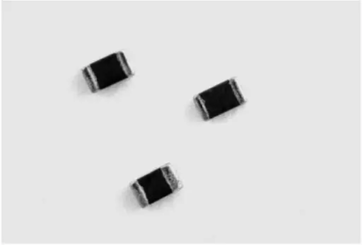
      Fig. 2.32: SMD-Multilayer inductor; image source: Würth Elektronik WE-MI

      Fig. 2.33: Structural schematics of multilayer SMD inductors

      The ferrite body magnetically shields the component, significantly reducing external interference and cross-talk. The multilayer inductor may be seen as a “compromise” between the ceramic inductor and SMD ferrite. This component is especially suitable as an inductor in filters and resonant circuits where low interference from external signals is required and in circuits with high packing density.

      Practical tips:
      • Do not operate in the self-resonant range

      • Observe max. current loading capacity

      • Low DC resistance, therefore also suitable for low-voltage systems

      Power Multilayer Inductors

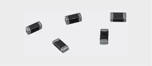
      Fig. 2.34: Power Multilayer Inductors ; image source: Würth Elektronik WE-PMI

      The miniaturization of SMD components, especially inductors, is a widespread trend in portable devices, as it is especially storage chokes that frequently require the most space. Wired components are out of the question in these orders of magnitude. This is where the power multilayer types apply.

      In order to allow minimization of the coil volume, the switching controller IC is driven at ever-higher switching frequencies. Switching controllers like the Micrel MIC2285 already work with 4 MHz. The dimensions of the storage chokes required can therefore be reduced by up to 90%. The compact power multilayer inductors in 1008 package (2.5 mm x 2.0 mm x 1.0 mm) not only offer high rated currents (up to 2.4 A), but also a lower DCR than comparable to standard multilayer inductors types.

      The saturation current of the power multilayer inductors (such as WE-PMIs) relates to the typical inductance drop of –30% from the zero current inductance. The rated current is defined for the common self-heating of DT = 40 K with respect to the ambient temperature.

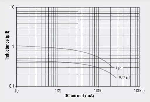
      Fig. 2.35: Inductance vs. DC current

      The used NiZn core material allows the use of the power inductors WE-PMI series up to 10 MHz. The multilayer types are especially suitable for power supplies in portable devices.

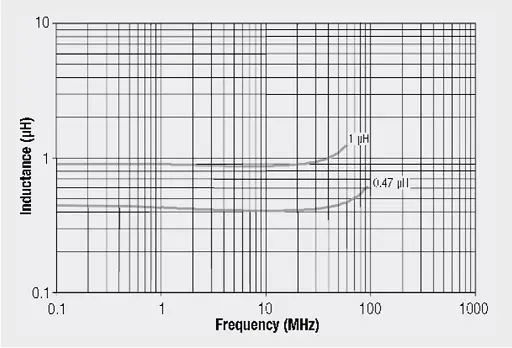
      Fig. 2.36: Inductance vs. frequency

      SMD – Wire Wound Inductor /SMD RF Inductor
      The wound SMD inductors (such as Würth Elektronik WE-GF and WE-LQ series) are available in SMD packages (Figure 2.37). They essentially differ in their mechanical construction. Whereas the WE-GF is completely embedded in plastic and can therefore handle high humidity very effectively, WE-LQ is in an open package. It can therefore be loaded with higher currents at the same inductance in relation to its package volume.

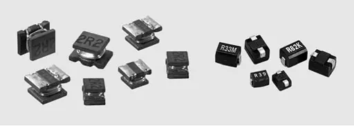
      Fig. 2.37: Wire Wound Inductor (WE-LQ left) and SMD RF inductor (WE-GF right)

      In Figure 2.38 the layout of the SMD RF Inductor is shown graphically. A wire-wrapping surrounds a ferrite body. The special ferrite mixture faciliates a wide inductance spectrum despite the miniature ferrite core.

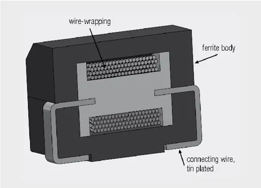
      Fig. 2.38: Inductor construction of resistor-type (WE-GF)


      ABC of CLR: Chapter L Inductors

      Coil with ferrite

      EPCI licensed content by: Würth Elektronik eiSos, Trilogy of Magnetics, handbook printouts can be ordered here.

      Creative Commons License
      This page content is licensed under a Creative Commons Attribution-Share Alike 4.0 International License.

      see the previous page: Design of optimized EMC filters for real operating environments

      < Page 12 >

      see the next page: Current compensated chokes

      Previous Post

      Design of optimized EMC filters for real operating environments

      Next Post

      Current compensated chokes

      Related Posts

      ABC of CLR

      RF Inductors and Filters

      ABC of CLR

      Power transformers

      ABC of CLR

      Telecom transformers

      Discussion about this post

      Categories

      • ABC of CLR
        • ABC of Capacitors
        • ABC of Inductors
        • ABC of Resistors
        • Mounting Guidelines
      • e-Symposium
        • ESA SPCD
        • PCNS
      • EPCI news
      • Market Insights
      • news collection

      Popular Posts

      • Transformer: Parasitic parameters and equivalent circuit

        1436 shares
        Share 574 Tweet 359
      • Transformer Calculation and Applications

        715 shares
        Share 286 Tweet 179
      • Introduction to Ceramic Capacitors

        521 shares
        Share 208 Tweet 130
      • Simulation with LTspice

        499 shares
        Share 200 Tweet 125
      • Dielectric Insulation Resistance, Capacitor DCL Leakage Current and Voltage Breakdown

        436 shares
        Share 174 Tweet 109

      Subscribe to Blog via Email

      Enter your email address to subscribe to this blog and receive notifications of new posts by email.

      © 2023 European Passive Components Institute

      No Result
      View All Result
      • Home
      • ABC of CLR
        • ABC of Capacitors
        • ABC of Inductors
        • ABC of Resistors
        • Mounting Guidelines
      • e-Symposium
      • EPCI Membership
      • About

      Welcome Back!

      Login to your account below

      Forgotten Password?

      Retrieve your password

      Please enter your username or email address to reset your password.

      Log In
      This website uses cookies. By continuing to use this website you are giving consent to cookies being used. Visit our Privacy and Cookie Policy.