


")


2.3 Power Inductors and Calculations
Switched-mode power supplies are becoming ever more widespread. The semiconductor manufacturers have made their contribution, offering a wide range these integrated circuits with simplified circuit design. Care must be taken in the selection of the appropriate storage choke to fully utilize the advantages of switching regulators.
The selection of cores and windings of storage chokes are optimized for use in switching converters and DC-DC converters.
Leading manufacturers of storage chokes following recommendations from various switching converter IC manufacturers, e.g. National Semiconductor, Linear Technology, STMicroelectronics, Texas Instruments, Exar, Diodes, MPS, ON Semiconductor, Semtech, Maxim and a special customized solutions can be found in their reference design guidelines.
Toroidal Core Types
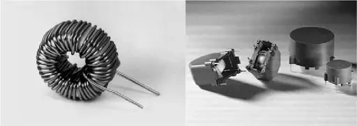
Fig. 2.42: Storage choke WE-SI and WE-GI
Toroidal storage chokes (such as Würth Elektronik WE-SI and WE-GI types) are ideal from the EMC perspective: The magnetic field lines mainly pass through the core. The stray field and associated coupling in neighboring conductor tracks or components remain small.
In the field of switching converters, storage chokes serve to buffer electrical energy and, at the same time, to smooth the output current.
The energy stored in the core in this process is:

To enable high energy storage and to minimize the resulting core losses, the toroidal core volume is divided into many electrically isolated regions. The iron powder used in our storage chokes therefore has three-dimensional, uniformly distributed, microscopic air gaps, which prevent eddy-current losses.
The disadvantage of reduced permeability is balanced by greater maximum energy storage and lower losses. Furthermore, these cores are extremely well suited for use in applications with high DC premagnetization.
Data book specifications
Open-circuit inductance L0:
If the inductor is operated without DC premagnetization or with only a small AC current, the open-circuit inductance L0 results.This value may be measured with sufficiently sensitive inductance measuring equipment for small AC voltages e.g. 0.1–0.5 V and a fixed measuring frequency between 1 kHz and 100 kHz, depending on the inductance value.
Inductance rating LN:
In addition to the small AC voltage amplitude, the specified DC current is superimposed and the resulting inductance measured.
Current rating IN:
The DC current, for which the inductance and wire thickness are specified and whose specifications are optimized. As shown in the graph below, inductance only saturates with a much larger current.
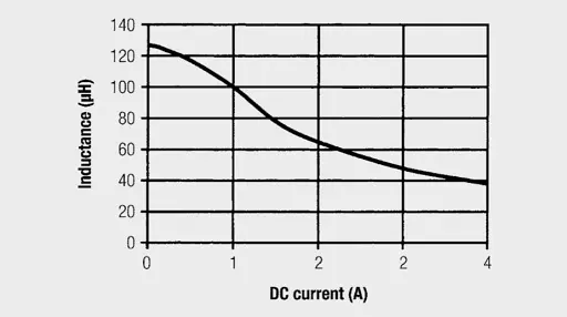
Fig. 2.43: Inductance with DC premagnetization; IN = 1 A; LN = 100 µH
DC resistance DCR:
The windings resistance value is measured with an ohmmeter at an ambient temperature of +25 °C.The test current for resistance measurement is a small DC current, which does not lead to a significant temperature increase in the wire. As values in the milliohm range are measured here, a 4-wire measurement must be made to minimize measurement errors.
Magnetic field energy E:
The energy, for which the core data and windings of the coil is optimized. This is specified in microjoules.The following simple and practically proven formulae can be used for dimensioning a storage choke. A brief extract from the extensive core material program and the following table should provide an overview of the choke dimensioning process. Depending on the application, further specifications from the core material data spectrum may be necessary.
Iron core material data:
The following table shows an overview of the most commonly used materials and their applications.
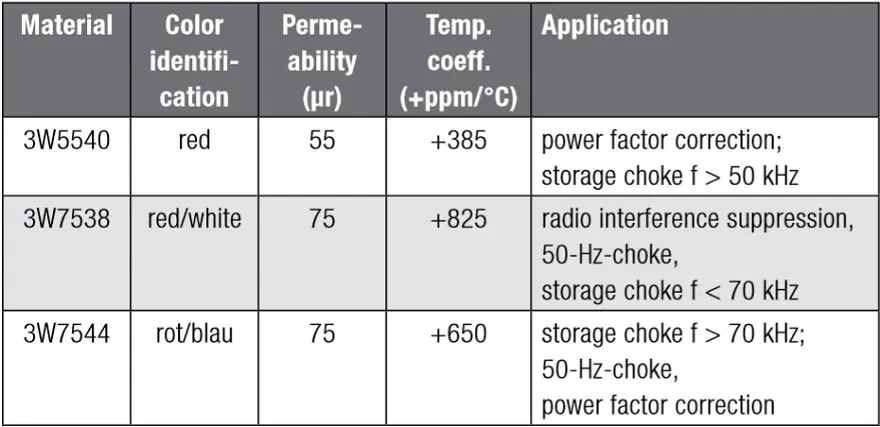
Tab. 2.22: Materials and their applications (source: Würth Elektronik)
Operating temperature:
The operating temperature of the iron powder core may be from –55 °C to +125 °C. Prolonged core operation above +75 °C however results in increased losses.
Insulation voltage:
The protective coating of the toroidal core uniquely identifies the core material and serves to protect against environmental effects and provides electrical isolation from the windings. Epoxy resin coatings are used and an insulation dielectric strength of 500 VDC is achieved as standard. Higher insulation voltages can also be offered.
AL value: For every size of core an AL value is specified to simply calculate the winding turns for the required choke; the tolerance is ±10%.
The standard means of measuring the AL value is at B = 1 mT and f = 10 kHz.
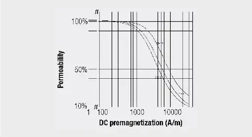
Fig. 2.44: Effective permeability with DC premagnetization
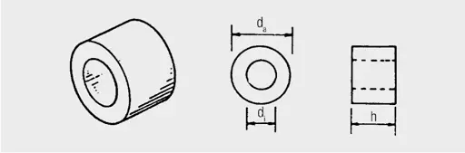
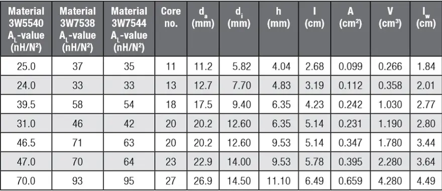
Tab. 2.23: Specifications of iron powder cores (source: Würth Elektronik)
- da = outer diameter
- di = inner diameter
- h = height
- l = effective magnetic length
- A = effective magnetic cross-sectional area
- V = effective magnetic volume l
- W = winding wire length for 1 turn
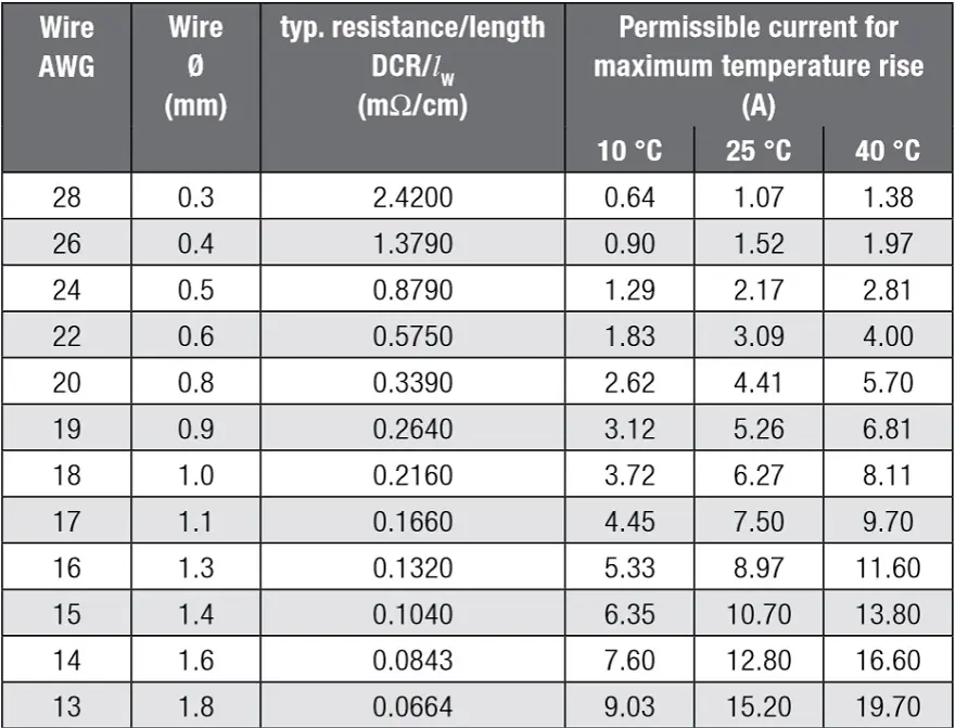
Tab. 2.24: Wire table (source: Würth Elektronik)
Storage choke calculation:
The following demonstrates how a storage choke can be calculated for a switching converter application:
Example: switching converter (step-down controller – storage choke)
Requirements:
Inductance rating LN = 100 µH Current rating (DC) IN = 1 A Peak current through the inductance Imax = 1.5 A Ripple current = 20% of Imax = 0.3 A (see Chapter III/Applications) Switching frequency f = 52 kHz
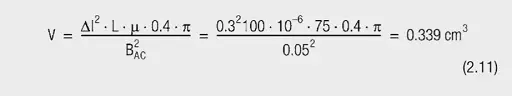
A maximum AC flux density BAC = 0.05 T is recommended for iron powder cores (to ensure low core losses). Also the inductance should be selected so the ripple current does not exceed 20%–30% of the maximum current.
Step 1: Choice of the core material and the necessary core volume (V) As the switching frequency is just 50 kHz, we firstly select the material 3W7538 with µr = 75.
Selected core:
3W7538, as switching frequency < 70 kHz; core no. 13 da = 12.7 mm; di = 7.7 mm; h = 4.83 mm
Magnetic data:
l = 3.19 cm; A = 0.112 cm2; V = 0.358 cm3 AL value: 33 nH/N2
Step 2: Required winding turns
L in nH
AL value in nH/N2

The final number of winding turns must be increased as a result of current dependent permeability. The correction factor for the AL value is determined from the “effective permeability against DC premagnetization” graph (see Figure 2.44).

At H = 1724 A/m on the graph in Figure 2.44
→ Effective permeability with DC premagnetization = 80% of the initial permeability
To be certain that the full inductance rating of 100 µH exists with a DC current of 1 A, the final number of winding turns is calculated as:

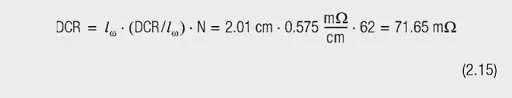
Step 3: Determination of the DC resistance
The wire diameter can be ascertained from the relevant wire tables for the required current of 1 A, e.g. AWG 22 (d = 0.6 mm). This limits the self-heating of the wire to less than +10 °C.
The DC resistance of the windings is given by:
Step 4: Check for max. AC field flux density
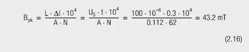
with:
- Inductance rating L in H
- Ripple current ΔI in A
- Core cross-sectional area A in cm2
- Winding turns N
- Peak voltage of the choke Us in V (during “t”)
- Duration of peak voltage t in s
Step 5: Calculation of core losses
The losses in the core material may be calculated from the following formula:
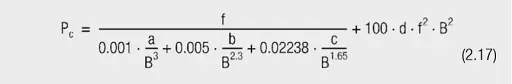
with
- Frequency f in Hz
- AC field flux density B in mT
- Core losses PC in mW/cm3
For our examples this leads to:
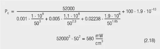
The total core losses of the selected core are:

The losses in the windings equal:

The total losses of the storage choke are low at around 370 mW and the choke calculated is well suited for the application.
ABC of CLR: Chapter L Inductors
Power inductors
EPCI licensed content by: Würth Elektronik eiSos, Trilogy of Magnetics, handbook printouts can be ordered here.

This page content is licensed under a Creative Commons Attribution-Share Alike 4.0 International License.


Discussion about this post