• Latest
  • Trending

LAN transformers

Toray to Boost Polypropylene Film Production to Meet Rising Automotive Capacitor Demand

Toray to Boost Polypropylene Film Production to Meet Rising Automotive Capacitor Demand

Yageo Expects Passive Components Inventory Correction for at Least Two Next Quarters

Yageo Expects Passive Components Inventory Correction for at Least Two Next Quarters

PCNS Passive Components Symposium 11-14th September 2023
Samtec High-Speed Interconnect Enable New Artix and Kintex UltraScale+ SoMs

Samtec High-Speed Interconnect Enable New Artix and Kintex UltraScale+ SoMs

May 2023 ECIA NA Electronic Components Sales Sentiment below April Expectation

May 2023 ECIA NA Electronic Components Sales Sentiment below April Expectation

Paumanok Issues Passive Components in Oil and Gas Electronics Market Outlook 2023-2028

Paumanok Issues Passive Components in Oil and Gas Electronics Market Outlook 2023-2028

Researchers Study Aluminum Dissolution to Increase Supercapacitor Voltages, Suggest New Way of Al Thin Film Deposition

Researchers Study Aluminum Dissolution to Increase Supercapacitor Voltages, Suggest New Way of Al Thin Film Deposition

Frenetic Offers Frenetic Zero One Month Free Magnetic Design Tool

Frenetic Offers Frenetic Zero One Month Free Magnetic Design Tool

Murata Releases 150C Automotive Crystals

Murata Releases 150C Automotive Crystals

KAMIC Group Acquires Wound Components Specialist AGW Electronics

KAMIC Group Acquires Wound Components Specialist AGW Electronics

4th PCNS Registration Opens !

  • Home
  • ABC of CLR
    • All
    • ABC of Capacitors
    • ABC of Inductors
    • ABC of Resistors
    • Mounting Guidelines

    RF Inductors and Filters

    Power transformers

    Telecom transformers

    LAN transformers

    Transformer Calculation and Applications

    Power Inductors 2 (cont.)

    Power inductors

    Current compensated chokes

    Coil with ferrite

    Trending Tags

      • ABC of Capacitors
      • ABC of Inductors
      • ABC of Resistors
      • Mounting Guidelines
    • e-Symposium
    • EPCI Membership
    • About
    No Result
    View All Result
    European Passive Components Institute
    • Home
    • ABC of CLR
      • All
      • ABC of Capacitors
      • ABC of Inductors
      • ABC of Resistors
      • Mounting Guidelines

      RF Inductors and Filters

      Power transformers

      Telecom transformers

      LAN transformers

      Transformer Calculation and Applications

      Power Inductors 2 (cont.)

      Power inductors

      Current compensated chokes

      Coil with ferrite

      Trending Tags

        • ABC of Capacitors
        • ABC of Inductors
        • ABC of Resistors
        • Mounting Guidelines
      • e-Symposium
      • EPCI Membership
      • About
      No Result
      View All Result
      European Passive Components Institute
      No Result
      View All Result
      Home ABC of CLR

      LAN transformers

      February 15, 2022
      Reading Time: 3 mins read
      179 3
      A A

      LAN and LAN RJ45 series Ethernet transformers

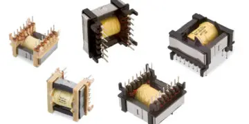
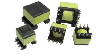
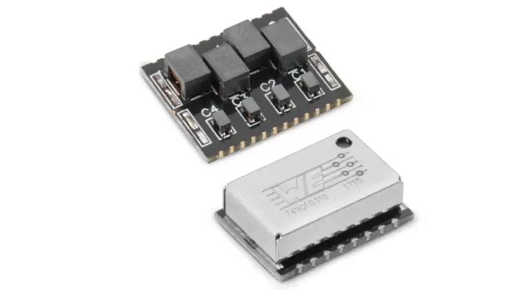
      The LAN Ethernet transformers (Figure 2.82) are not simple transformers, but rather modules in which, depending on the number of ports for which they are suitable, at least two transformers and a certain number of current-compensated chokes are contained.
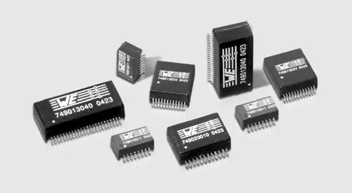
      Fig. 2.82: LAN transformers

      As the name denotes, they are designed as transformers for Ethernet networks. Ethernet is the most widespread form of local network (Local Area Network – LAN). Ethernet is operated at different transmission speeds. The requirements for Ethernet are described in the IEEE802.3 standards:

      • 10 Base-T: transmission rate 10 Mbps > standard IEEE802.3

      • 100 Base-T: transmission rate 100 Mbps > standard IEEE802.3u

      • 1000 Base-T: transmission rate 1000 Mbps > standard IEEE802.3ab

      • Power over Ethernet: independent of the transmission rate > IEEE802.3af

      For these standards, the transmission medium is a copper cable with unshielded, twisted pairs (UTP) of type CAT5 or better. The other IEEE802.3 series standards refer to glass fibre cable transmission.

      For 10 Base-T and 100 Base-T, one wire pair is used for the transmission channel (transmit) and one for the reception channel (receive). Two of the four wire pairs in the Cat5 cable remain unused. In the case of 1000 Base-T, all four wire pairs are used in both directions.

      According to the EN60950 standard (safety of information technology equipment), Ethernet is classified as a TNV 1 circuit (telecommunication network voltage). It has to be isolated against a SELV circuit (safe extra low voltage). The test voltage stipulated by the standard must be at least 1.5 kV with a test duration of 1 min.

      As a result of this isolation voltage, it is essential to use a transformer between the network and the Ethernet terminal device. So two transformers are required for 10/100 Base-T networks and four transformers for 1000 Base-T networks. The necessary number of transformers is integrated in the WE-LAN series modules. As described in the previous section, ring core transformers are used.

      To avoid further external components, e.g. current-compensated chokes (data line filters), these are also integrated in the transformer modules (see Figure 2.83).
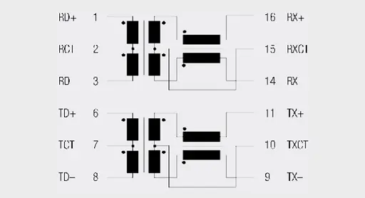
      Fig. 2.83: Typical circuit diagram for a LAN transformer module

      The relevant Ethernet standards for 100 Base-T call for transformers with a minimum inductance of 350 µH and DC current premagnetisation of 8 mA. This should serve to ensure functionality even with small asymmetries of the wire pairs.

      The turns ratio is defined by the Ethernet controller used. Whereas 10 Base-T often uses turns ratios of 1 : 1.414 or 1 : 2.5 on at least one of the lines, 100 and 1000 Base-T almost exclusively work with a turns ratio of 1 : 1. This is because the number of secondary turns is so large – due to the high primary inductance combined with a higher number of turns than with 10 Base-T – that they can no longer be accommodat ed on a small ring core. Winding with twisted wires is also no longer possible, which can still be tolerated for 10 Base-T, but leads to a de terioration in transmission properties for 100 Base-T.

      The minimum insertion loss and the maximum values for return loss, crosstalk and common mode rejection are also defined over the entire frequency range.
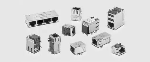
      Fig. 2.84: LAN RJ45 transformer integrated RJ45 connector


      ABC of CLR: Chapter L Inductors

      LAN transformers

      EPCI licensed content by: Würth Elektronik eiSos, Trilogy of Magnetics, handbook printouts can be ordered here.

      Creative Commons License
      This page content is licensed under a Creative Commons Attribution-Share Alike 4.0 International License.

      see the previous page: Applications for transformers

      < Page 17 >

      see the next page: Telecom transformers
      Previous Post

      Open Letter to AEC-Q200 Committee on MLCC DC BIAS Ageing Capacitance Loss Issues

      Next Post

      Telecom transformers
      Related Posts

      ABC of CLR

      RF Inductors and Filters

      889
      ABC of CLR

      Power transformers

      727
      ABC of CLR

      Telecom transformers

      569

      Discussion about this post

      Categories

      • ABC of CLR
        • ABC of Capacitors
        • ABC of Inductors
        • ABC of Resistors
        • Mounting Guidelines
      • e-Symposium
        • ESA SPCD
        • PCNS
      • EPCI news
      • news collection

      Popular Posts

      • Transformer: Parasitic parameters and equivalent circuit

        1312 shares
        Share 525 Tweet 328
      • Transformer Calculation and Applications

        691 shares
        Share 276 Tweet 173
      • Introduction to Ceramic Capacitors

        481 shares
        Share 192 Tweet 120
      • Simulation with LTspice

        474 shares
        Share 190 Tweet 119
      • Insulation Resistance, DCL Leakage Current and Voltage Breakdown

        420 shares
        Share 168 Tweet 105

      EPCI Membership

      join passive components community

      © 2023 European Passive Components Institute

      No Result
      View All Result
      • Home
      • ABC of CLR
        • ABC of Capacitors
        • ABC of Inductors
        • ABC of Resistors
        • Mounting Guidelines
      • e-Symposium
      • EPCI Membership
      • About

      Welcome Back!

      Login to your account below

      Forgotten Password?

      Retrieve your password

      Please enter your username or email address to reset your password.

      Log In
      This website uses cookies. By continuing to use this website you are giving consent to cookies being used. Visit our Privacy and Cookie Policy.