


")


2.2 Current compensated chokes
Saturation effects caused by high signal currents, or DC current super imposed on the signal, reduce the effectiveness of the choke. The use of standard inductors in the signal path adversely impairs the useful signal. Current compensation circumvents these disadvantages. In current compensation, the “useful return current” must be passed through the choke. In this way, the useful current does not contribute to the magnetization of the core.
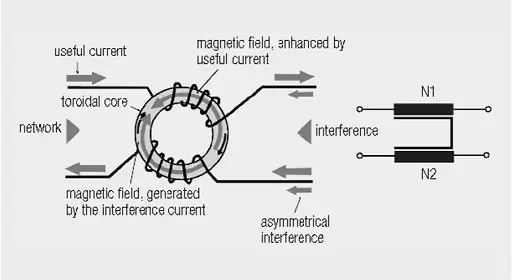
Fig. 2.39: Construction and circuit diagram of a current compensated choke
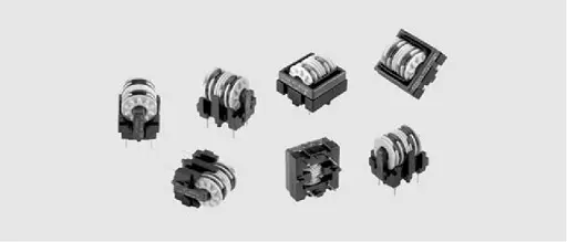
Current-compensated chokes can be manufactured with different ferrite geometries; the best known are ring core and ribbed core. Different core materials enable their use in various frequency ranges. A very well known component, but one not designed as a common mode choke, is the snap ferrite or the split ferrite sleeve.
The effect of current-compensated chokes on coupled interference is, above all, used for data and signal lines. They are often the only option to avoid the interference suppression component affecting the useful signal.
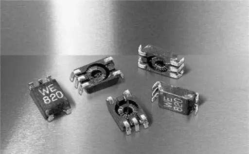
SMD Common Mode Noise Suppressor
Sizes: 0805; 1206
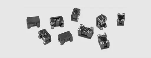
The SMD Common Mode Noise Suppressor (such as Würth Elektronik WE-CNSW) is usually not based on a ring core, either in size 0805 or 1206. Only for this reason it is possible to achieve such a compact current-compensated component.
However, as it is a closed ferrite material system, the stray field remains negligibly small. Typical applications for the SMD common mode noise suppressors are USB, Firewire or High Speed Data Lines.
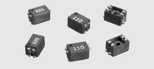
Current-compensated SMD filter
In contrast to SMD common mode noise suppressors, the current-compensated SMD line filters (such as Würth Elektronik WE-SL series), include ring cores. As a result, stray fields can almost be excluded. The different geometries and, above all, the very flat package heights of the various types, offer potential solutions for every application.
High current ratings, as used in low-voltage applications, are also available.
Despite their compact construction, the current-compensated SMD line filters can also offers 4x current-compensated versions.
NiZn core current-compensated SMD filter
The NiZn current-compensated SMD line filters (such as Würth Elektronik WE-SLM series) offers high in common mode impedance with a smaller footprint than MnZn types. NiZn ferrite base material provides a wider working temperature range.
At the same time, the leakage inductance is lower so the signal is less affected. The NiZn core current-compensated SMD line filters can therefore also be used at high signal frequencies.
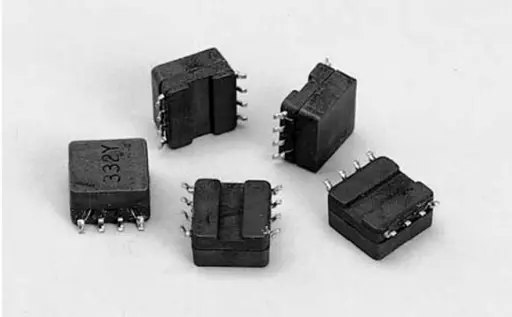
MnZn current-compensated SMD filter
The MnZn current-compensated SMD line filter (such as Würth Elektronik WE-SL1 series) all excels by virtue of its low space requirement, both in terms of package height as well as footprint. The manganese-zinc basic material provides adequate balances attenuation values.
MnZn current-compensated SMD filter with separated construction
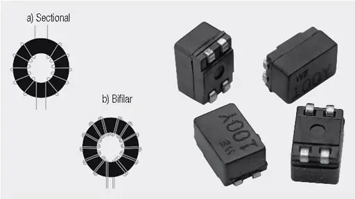
The MnZn current-compensated SMD line filters can be prepared also with separated construction and both sectional and bifilar winding technology. (such as Würth Elektronik WE-SL2 series). The separated construction of the sectional winding allows both the attenuation of high frequency symmetrical frequency components, as well as the suppression of asymmetrical interference components. However, if the quality of the useful signal is too greatly affected, the original bifilar winding technology should be chosen.
MnZn current-compensated SMD filter with separated high-density construction

The MnZn current-compensated SMD line filter with separated construction can be also made in high density version (Würth Elektronik WE-SL3 series) that represents an advancement of the MnZn current-compensated SMD line filters. Despite the halved package height, almost the same performance can be attained, at least for low inductance values. Additionally a 3x current-compensated version has been developed, which is mainly used for low voltages.
High frequency MnZn current-compensated SMD filter
A special high frequency design of manganese-zinc (such as Würth Elektronik WE-SL3 series above) allows the frequency band in the single and double figure megahertz range to be covered.
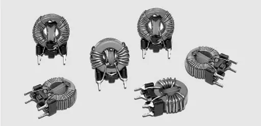
Current compensated choke for mains voltage applications
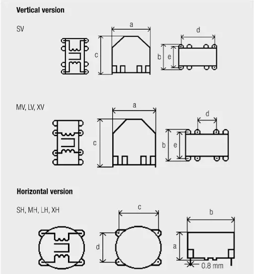
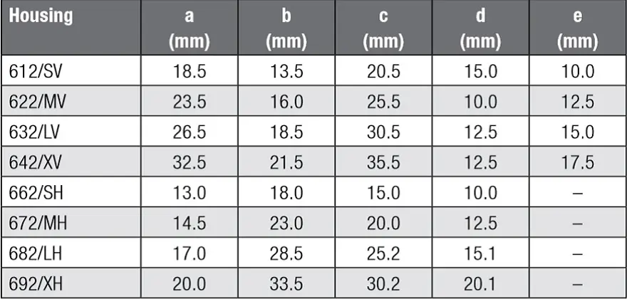
Tab. 2.18: Dimensions of the current compensated choke; Würth Elektronik WE-LF
The maximum permissible component temperature of the WE-LF component series is +125 °C. If the permissible excess temperature of 55 K is subtracted, an allowable ambient temperature of +70 °C still remains. For even higher temperatures, the rated current must be reduced according to the following formula.

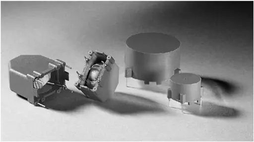
Current-compensated choke for mains applications – advanced design
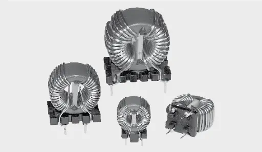
Special construction of the current-compensated choke (WE-CMB) allows the reduction of undesirable parasitic effects for mains applications. The almost perfectly selected core/winding relationship allows a very high current for a comparable footprint.
However, if conducting components or packaging parts are placed in the immediate vicinity, the required safety separation must be ensured, as enameled wires are not considered to be insulated components. In most cases, the use of this design, however, unproblematic as insulated components, such as capacitors, provide the necessary separation.
NiZn Current Compensated Choke
The NiZn variants are a specialty within the current-compensated chokes for mains applications and it can be available in more sizes (such as Würth Elektronik WE-CMB NiZn XS and S). In contrast to comparable mains chokes, nickel-zinc is used here as the base material. This makes it possible to effectively suppress asymmetric interference components up to the high frequency range.
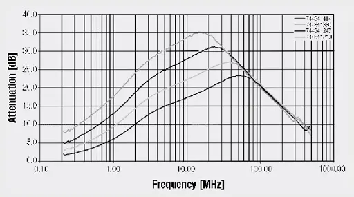
Fig. 2.40: Insertion loss (common mode) “WE-CMB NiZn Type XS”

Fig. 2.41: Insertion loss (common mode) “WE-CMB NiZn Type S”
This product variation is also suitable for increasing the interference immunity against incident RF radiation and burst signals. The main frequency component of the interference phenomena mentioned is within the working range of the choke and can therefore be effectively attenuated.
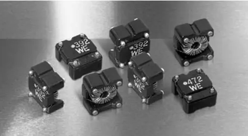
Multi-chamber Current-Compensated Power Line Choke WE-FC
Multichamber current-compensated choke (such as Würth Elektronik WE-FC) has roughly twice the leakage inductance relative to comparable toroidal chokes. The effect on symmetrical interference increases without having to use an additional inductor. Parasitic parallel capacitance is reduced as a result of the construction with a multi-chamber coil body.
The impedance profile is raised at higher frequencies. At the same time, resilience against burst and surge pulses is improved.
ABC of CLR: Chapter L Inductors
Current compensated chokes
EPCI licensed content by: Würth Elektronik eiSos, Trilogy of Magnetics, handbook printouts can be ordered here.

This page content is licensed under a Creative Commons Attribution-Share Alike 4.0 International License.


Discussion about this post