This article based on blog by Pablo Blázquez, Frenetic power electronics engineer is exploring the innovative domain of Power Electronics putting the spotlight on the Dual Active Bridge (DAB) topology and its impact on various applications.
Let’s discover why and when DAB topology emerges as a great choice, alongside real-life examples that show its efficiency and versatility.
What is DAB Topology?
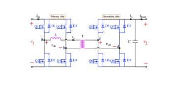
The Dual Active Bridge (DAB) topology is a type of power conversion architecture used in various applications, from renewable energy systems to electric vehicle chargers. At its core, the DAB includes two sets of Power Electronic switches connected to two transformers, creating a bidirectional power flow path.
Here’s a simplified breakdown of how the DAB works (see circuit on featured image):
Input Stage
The input stage consists of power electronic switches (typically MOSFETs or IGBTs) that control the flow of power from the input source, such as the grid or a renewable energy generator, to the DAB.
Isolation Stage
The two transformers within the DAB provide electrical isolation between the input and output stages, allowing for safe operation and voltage conversion.
Output Stage
Similar to the input stage, the output side of the DAB also features power electronic switches that regulate the flow of power to the load or grid.
Control and Regulation
A sophisticated control algorithm governs the switching of the power electronic devices, ensuring efficient power transfer and regulation of the output voltage or current according to the application requirements.
Why Dual Active Bridge (DAB) Topology?
DAB topology stands out as a game-changer in Power Electronics for several reasons. It offers remarkable efficiency levels, making it an attractive option for applications where minimizing energy loss is crucial. With its ability to handle a broad range of input and output voltages, DAB topology proves to be versatile and adaptable to diverse power system requirements.
Dual Active Bridge also facilitates effective isolation and regulation of power, enabling seamless integration into various systems while ensuring reliable operation. Moreover, compared to traditional power conversion topologies, DAB offers the advantage of compactness and reduced weight, making it ideal for applications where space and weight constraints are critical.
Real-Life Applications
Now, let’s explore concrete examples showcasing the applications of DAB topology:
Electric Vehicle (EV) Charging Infrastructure
In the rapidly expanding electric vehicle sector, efficient and rapid charging infrastructure is fundamental. DAB topology finds its place in high-power charging stations, enabling fast and reliable power conversion, contributing to the widespread adoption of electric vehicles.
Renewable Energy Integration
With the global shift towards renewable energy sources, such as solar and wind, the need for efficient power conversion solutions becomes imperative. DAB topology facilitates the integration of renewable energy systems into the grid, enabling an easy conversion and transmission of power with minimal losses.
Data Centers and Server Farms
Data centers and server farms demand robust and efficient power distribution solutions to support their intensive computing operations. DAB topology offers a scalable and reliable solution for power distribution within these facilities, optimizing energy usage and reducing operational costs.
Industrial Applications
From manufacturing plants to heavy machinery, industrial applications require dependable power conversion solutions to ensure uninterrupted operations. DAB topology proves invaluable in industrial settings, providing efficient and precise power conversion tailored to the specific needs of each application.
High-Performance Computing (HPC)
In the domain of high-performance computing, where power demands are high and efficiency is paramount, DAB topology offers an optimal solution for power distribution and conversion. It helps meet the stringent power requirements of HPC systems while minimizing energy wastage.
DAB vs. LLC Topology: A Comparison
While both DAB and LLC topologies are renowned for their efficiency and versatility, they differ in several aspects.
First of all, their topology structure: DAB employs two active switches on both primary and secondary sides, providing bi-directional power flow control, while LLC utilizes resonant tank components, offering soft-switching characteristics and high efficiency.
As far as the voltage Range is concerned, DAB excels in handling a wide range of input and output voltages, making it suitable for various applications with diverse voltage requirements. LLC topology is typically employed in applications with fixed voltage levels.
While DAB control requires sophisticated algorithms to manage the bidirectional power flow and ensure efficient operation, LLC control is relatively simpler, focusing on resonant tank behavior for optimal performance.
DAB and LLC also differ in their applications: DAB is well-suited for applications requiring bidirectional power flow control, such as EV charging stations, renewable energy systems, and high-performance computing. LLC finds its application in power supplies, server power modules, and LED lighting systems.
Conclusion
In conclusion, the Dual Active Bridge topology stands at the forefront of Power Electronics innovation, offering unparalleled efficiency, versatility, and reliability across a wide range of applications. Its adoption continues to grow, driven by the increasing demand for energy-efficient and sustainable power solutions in today’s dynamic landscape.
Read the original post at Dual Active Bridge (DAB) Topology Explained
