


")


L.1.6 Permeability μ
Permeability describes an important effect in ferromagnetic materials. If a ferromagnetic material is placed in a magnetic field, it is observed that the magnetic flux becomes concentrated in this material. Analogous to electric resistance, the ferromagnetic material presents a good conductor for the field lines. Permeability may therefore be described as a magnetic conducting or penetrating property.
Featured Image Fig. 1.16: Ferromagnetic material in a magnetic field
The factor by which the induction (B) changes through the introduction of the material is called the relative permeability (μr).
The equation for relative permeability is extended for the space filled by the material:

The induction in the core material (BF) in our example on page 19 (a constant permeability of μr = 800 is assumed) is given by:

The relative permeability of the material is however not constant but strongly non-linear. The permeability of a material is essentially dependent on:
- The magnetic field strength H (dependent on operating conditions → hysteresis curve)
- The frequency f (frequency dependent complex permeability)
- The temperature T (→ temperature drift, → Curie temperature)
- The material used
Typical permeabilities (μr):
- Iron powder cores, superflux cores 50 … 150
- Manganese-zinc cores 300 … 20000
- Nickel-zinc cores 40 … 1500
L 1.6.1 Complex permeability

Fig. 1.17: Frequency dependence of permeability and impedance

The introduction of complex permeability allows separation into an ideal (zero loss) inductive component and a frequency dependent resistive component which represents the losses of the core material. This treatment can be applied to all core materials and clearly differentiates between inductors and EMC ferrites.
The inductive component is represented by (μI) and the resistive component by (μII). The following applies to transformation on the impedance level:

with L0 = inductance of an air coil of the same construction and field distribution, without core material (μr = 1).
For the series impedance (Z):
 Fig. 1.18: Equivalent impedance circuit diagram

Multiplying out and dividing into real and imaginary parts provides the following relationship:
- Loss component RS = ωL0μSII
- Inductance component XLS = ωL0μSI

Fig. 1.19: Loss angle (δ)
For the loss angle (δ), tan δ is given by:
A large angle (δ) means a high core loss; the phase relationship between voltage and current at the inductor is less than 90°.
Furthermore:
μSI = μi
μSII = μi · tan δ
(μi = initial permeability)
Similarly, inductance and resistance can also be presented as a parallel equivalent circuit; the following relationships apply:

These frequency dependent components can be measured with the aid of impedance analysis and represented in an associated graph:
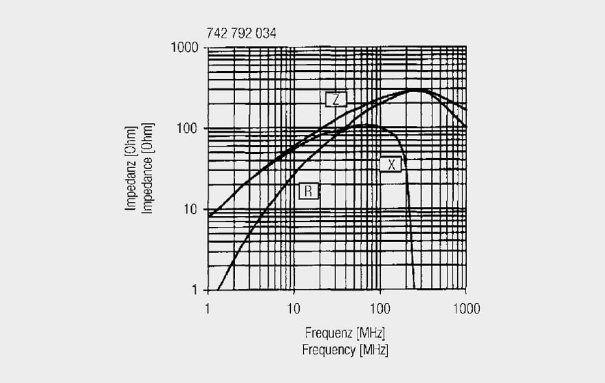
Fig. 1.20: Impedance curve for SMD ferrite 742 792 034
Observations from the above measurement graph:
- The inductance is stable in a certain frequency range, to show strong frequency dependence above approx. 10 MHz.
Above 100 MHz the inductance falls sharply, down to zero at approx. 250 MHz. - The loss component (R) grows continuously with frequency and reaches the same value as the X component at the so-called ferromagnetic resonance frequency. The
resistance value rises until the high MHz range and dominates over the impedance (Z).
The component shown here – a SMD ferrite – serves the user as a broadband absorber or filter component, as a result of its broadband loss resistance (R).
1.6.2 Comparing core materials
Core materials are only used effectively in the construction of inductors within a limited frequency range, as a result of the frequency dependent loss components. Core losses rise sharply above a typical frequency limit. The core material may then be used then as a filter component.
This relationship and also the limits of core materials are illustrated in the following graph:
 Fig. 1.21: Inductive parts of impedance and their frequency dependence for various core materials

Fig. 1.22: Resistive parts of impedance and their frequency dependence for various core materials
Observations:
- Iron powder materials (Fe): May be used as pure inductance up to approx. 400 kHz; the R loss component dominates thereafter up to approx. 10 MHz (also beyond depending on the core material). The core is no longer effective in the frequency range above approx. 20 MHz.
- Manganese-zinc cores are inductive up to frequencies around 20 MHz – 30 MHz, typically with losses rising above 10 MHz. The core material is no longer effective in the frequency range above –approx. 80 MHz.
- Nickel-zinc cores are inductive up to frequencies around 60 MHz, above this, the core material shows losses up to frequencies of 1 GHz and more.
This quantitative comparison illustrates why nickel-zinc ferrites have become predominant in the EMC field. The core material can perform an effective filter function in the frequency range of greatest interest.
ABC of CLR: Chapter L Inductors
Permeability μ
EPCI licensed content by: Würth Elektronik eiSos, Trilogy of Magnetics, handbook printouts can be ordered here.

This page content is licensed under a Creative Commons Attribution-ShareAlike 4.0 International License.
see the previous page:
< Page 4 >
see the next page:


