The aim of this survey is to collect and summarise mounting recommendations of publicly available information from capacitor and resistor commercial component manufacturers.
The survey aim is to collect the manufacturer’s recommendations and good tips for capacitors and resistor mounting BEYOND the industry standards. The survey doesn’t aim to provide a complete mounting procedure guidelines as part of specific industrial requirement and standards.
Capacitor and Resistor Manufacturers Public Sources Included in the survey:
Capacitor Manufacturers:
- AVX
- Cobham Microwave
- Exxelia
- Kemet
- Murata
- Nichicon
- Nippon Chemicon
- Taiyo-Yuden
- TDK
- Semco
- Panasonic
- Vishay
- Walsin
- Yageo
Resistor Manufacturers:
- Ampcontrol
- Arcol
- Cressall Resistors
- HVR Pentagon
- Isabellenhütte Heusler
- Japan Resistor Manufacturing
- KOA Speer
- Murata
- Ohmite
- Panasonic
- Rohm
- TE Connectivity
- Telema Precision Resistor Company
- Vishay (USA)
Introduction
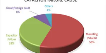
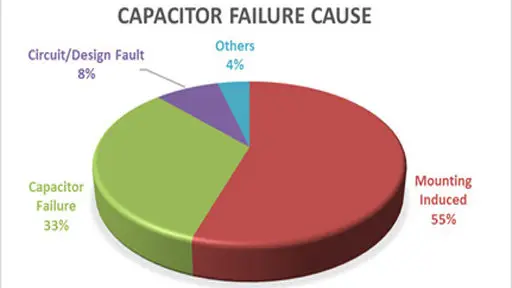
Mounting related induced failures are the number one reason (over 55%) for the field application capacitor failure causes according to a EPCI end customer survey – see featured Fig.1.
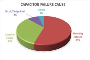
The capacitor component failures itself represents “just” 33% of the root failure causes. Thus, a careful evaluation of mounting guidelines and follow up in real assembly processes per the component manufacturers’ recommendations shall be considered as a critical characteristic. This mounting guide survey report summarizes recommendations of ESCC QPL capacitor and resistor technology (including both QPL and other commercial manufacturers) and present some recommendations, tip & tricks for the best mounting practice published by component manufacturers. Space requirements, as specified in ECSS standards, are not included in this guide.
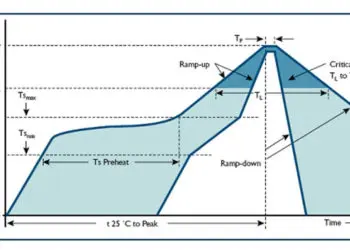
Board mounting soldering processes itself shall be adapted to contradictory requirements. On one hand, a certain minimum time in the molten solder to get a good wetting is needed and on the other hand, as short exposure to the molten solder as possible to minimize any risk of damage on component. The following items to be considered for selection of the proper mounting technique and its parameters:
- many times mounting process is „the worst electrical and mechanical stress in the component’s life“
- thermal stress may damage parts by excessive heat
- thermal stress may cause issues due to CTE mismatch
- degradation by thermally driven wear out mechanisms – diffusion, migration, increase of chemical activity …
- component history (packaging, transport) may play a key role
- strong absorbed humidity and oxidisation impact
- pre-tinning and re-soldering (SnPb solder dip) requirements
- rework option and conditions
- temperature exposure is directly proportional to the post reflow failures and ppm life failures
- PCB construction, number of layers, technology used, required volume and soldering process repeatability
- handling of components (manual/pick & place) and PCB (mechanical shock, vibration, rack/holder loading, support pins use, screwing position/sequence/force, …)
ABC of CLR: Chapter M Mounting Guidelines
Introduction
EPCI licenced content by:
EPCI European Passive Components Institute experts original articles
Acknowledgement
The presented guidelines have been prepared under ESA Contract: 40001210761/17/NL/CRS with European Passive Components Institute s.r.o. “Passive Component Support EEE331”

This page content is licensed under a Creative Commons Attribution-Share Alike 4.0 International License.
