xDSL Digital Subscriber Line transformers
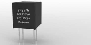
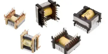
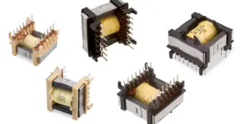
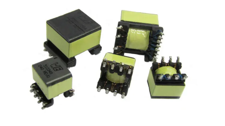
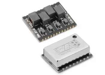
The xDSL Digital Subscriber Line transformers (Figure 2.85) are specialized line interface transformers that are designed to optimise the performance of DSL chipsets. With each chipset varying in power drive levels, impedance characteristics and signal spectrum the transformers are very much chipset dependant in their design.
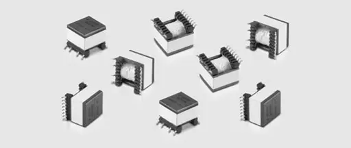
Fig. 2.85: DSL Digital Subscriber Line transformers
DSL (Digital Subscriber Line)
DSL technology has its origins in the competition between the telecom and cable television industry to offer each other’s services; video and data services. While the hybrid fiber/coax cable network was already a high-bandwidth network, the telecom industry had to look to some other technology to increase the bandwidth of their aging analog network.
ADSL (Asymmetrical Digital Subscriber Line)
The ADSL technology formed the backbone of the telecom industry’s initial foray into the high speed data and video services market. Asymmetrical in nature, the ADSL technology reserves the bulk of the available bandwidth for down loading data rather than uploading. This is consistent with the requirements of video services as well as the traffic pattern of the typical internet user. ADSL data rates generally are in the 1 to 16 Mbits/s downstream and 1 to 2 Mbit/s upstream with POTS service concurrently available on the same line. Various flavours and generations of ADSL are, and have been, promoted such as ADSL2, ADSL2+, ADSL+, RADSL, etc.
HDSL (High-Speed Digital Subscriber Line)
Following on the heels of ADSL technology was HDSL which addresses the needs of those users requir ing a symmetrical service with as much bandwidth available for upstream data traffic as downstream. The HDSL services are targeted to service providers, businesses and Small Office Home Office (SOHO) customers. Generally speaking the HDSL technology is a replacement for the older T1/E1 technology. Like ADSL, the HDSL technology is promoted in a host of variants such as SHDSL, SDSL, HDSL-2, HDSL-4 MDSL, IDSL, g.SHDSL etc.
VDSL (Very High Speed Digital Subscriber Line)
The latest generation DSL technologies are the VDSL and VDSL2 technologies. VDSL and VDSL2 increases the maximum available download bit rate to over 100 Mbit/s at short loop lengths. VDSL technologies allow for either symmetric or asymmetric access and support high bandwidth applications such as HDTV in addition to telephone and data services.
Transformer Parameters
Inductance:
Inductance requirements vary widely between not only DSL technologies, but also between chipsets. ADSL and VDSL inductance requirements can be below 100 µH while HDSL inductance specifications are over 3 mH. Depending on the specific requirements of the chipset this inductance can be any value in between and is almost always toleranc ed to a level of ± 5 to 10 percent. The inductance specification is almost always specified by the IC manufacturer and is dependant on a host of conflicting requirements including:
- The transformer’s need to handle DC current
- Whether or not the transformer has to perform a filtering function for concurrent POTS operations
- Signal bandwidth
- The insertion loss
- The return loss characteristics
- The impedance characteristics of the chipset
DC current handling:
Typically only HDSL type technologies require the transformer to operate with a DC current applied through the transformer. This requirement is due to the fact that HDSL type equipment is often called on to provide power to remote terminal devices. Typical DC current requirements for HDSL products are 60 to 100 mA.
Turns ratio:
Turns ratios, like inductance, can vary greatly from chipset to chipset. While most transformers have a single primary and secondary winding, it is not uncommon for some chipsets to require separate secondary windings for transmit and receive or even a separate auxiliary winding. Factors affecting the turns ratio include:
- The architecture of the chipset
- The return loss characteristics required
- The impedance characteristics of the chipset
- Whether or not the signal voltage needs to be stepped up or down
Leakage inductance:
Leakage inductance requirements are almost always held to a maximum value. In rare instances where the chipset is particularly sensitive to variations in impedance, the leakage inductance will be held to a tolerance requirement. While this is possible to achieve, it does result in a design that is very susceptible to variations in manufacturing and should be avoided if at all possible. Factors that dictate the leakage inductance specification include:
- The insertion loss requirements
- Signal bandwidth
- The return loss characteristics required
- The impedance characteristics of the chipset
Interwinding capacitance:
Interwinding capacitance may or may not be specified by the IC manufacturers when defining the transformer requirements depending on the transceivers sensitivity to capacitance. However, regardless of whether or not it is specified, interwinding capacitance affects the overall performance and is typically limited by the following requirements:
- The insertion loss
- Signal bandwidth
- The return loss characteristics
- The impedance characteristics of the chipset
- Longitudinal balance
DC resistance:
Besides affecting the power transfer efficiency of the transformer, DC resistance also affect to a lesser degree these DSL line transformer requirements:
- The insertion loss requirements
- The return loss characteristics
- The impedance characteristics of the chipset
- Longitudinal balance
Total harmonic distortion:
General: The total harmonic distortion THD denotes the ratio of the effective value of all harmonics of a signal to the effective value of the total signal.

For sinusoidal signals, the total harmonic distortion is used as a measure of non-linear distortions! The smaller the THD, the more the signal corresponds to the original!
Total harmonic distortion is a measure of how much the DSL transformer will distort the desired signal. The harder a transformer is driven, the more the core approaches saturation. As the core approaches saturation the signal begins to distort. While total harmonic distortion is a concern for all DSL transformer, it is not as critical for VDSL transformers where the operation of the core is at higher frequency; hence a lower flux density and further away from saturation. HDSL transformers however utilize the lower end of the frequency bandwidth quite extensively and are often driven quite hard at these frequencies for longer loop lengths. This results in a need for good total harmonic distortion characteristics at a high flux density level.
Crosstalk:
While crosstalk is always a concern for IC manufacturers, it is typically not an issue with the line interface transformers. Almost all line interface transformers for DSL are constructed on some EP style of core which is by virtue of its’ shape, self shielding.
Voltage/safety isolation:
Voltage/safety isolation is always a consideration as it is the primary purpose of the DSL line interface transformer in the first place. Depending on the safety agency requirements and intended application the isolation as well as creepage and clearance requirements for the transformer will vary. Typically transformers need to supply basic or supplementary isolation for a working voltage of 250 V per the IEC60950 standard. In summary each of these parameter affect the others to a greater or lesser degree. The crux of DSL line interface design is balancing all of these parameters to create a solution that meets the customer requirements in a cost effective manner.
ABC of CLR: Chapter L Inductors
Telecom transformers
EPCI licensed content by: Würth Elektronik eiSos, Trilogy of Magnetics, handbook printouts can be ordered here.

This page content is licensed under a Creative Commons Attribution-Share Alike 4.0 International License.









Discussion about this post