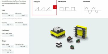
This article is based on newsletter written by Pablo Blázquez, Frenetic power electronics engineer that explores a key player in power supply design, the Flyback Transformer.
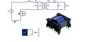
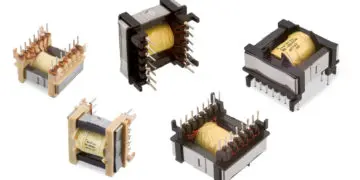
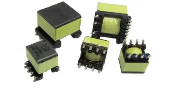
The Flyback Transformer, also known as a Flyback Converter, serves as a fundamental pillar in the domain of Power Electronics. This sophisticated Magnetic component facilitates energy transfer between input and output circuits, utilizing Magnetic fields to store and release energy.
Unlike conventional transformers, its distinctive feature lies in its capacity to store energy during one phase of the input cycle and discharge it during another, enabling a variety of applications.
When and how to use Flyback Transformers
Flyback Transformers emerge as an optimal solution in scenarios demanding galvanic isolation, high voltage tolerance and stable output under varying loads. Consider the following scenarios highlighting the strategic application of Flyback Transformers:
- Power Adapters: Flyback Transformers find their place in power adapters for electronic devices, ensuring user safety through galvanic isolation and safeguarding sensitive electronics.
- LED Drivers: the adaptability of Flyback Transformers proves beneficial in LED driver applications, efficiently managing fluctuating loads to maintain a consistent output voltage crucial for LED lighting systems.
- Low Power Isolation: in applications that require minimal power transfer across an isolation barrier, such as feedback circuits or sensors, the compact and efficient nature of flyback transformers is advantageous.
Flyback Transformers Topologies
Flyback Transformers exhibit a variety of topologies, each tailored to specific requirements. In addition to the conventional topologies discussed earlier, a relevant configuration is the Active Clamp Flyback Transformer.
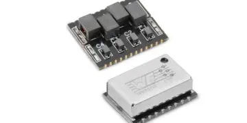
This innovative topology enhances the performance of traditional Flyback Transformers by incorporating an active clamp circuit. The active clamp feature helps mitigate voltage spikes and minimizes stress on components, leading to improved efficiency and reliability in high-power applications.
- Enhanced Efficiency: the active clamp mechanism contributes to reduced switching losses, enhancing overall efficiency in power transfer.
- Stress Mitigation: by controlling voltage spikes and minimizing stress on components, the active clamp design ensures a longer lifespan for the Transformer and associated electronics.
- High-Power Applications: particularly beneficial in high-power applications, the Active Clamp Flyback topology addresses challenges posed by increased power demands.
In summary, the Active Clamp Flyback Transformer represents a cutting-edge approach to power supply design, offering enhanced efficiency and durability in demanding applications.
Other Topologies
The Single-Output Flyback is Ideal for applications that need a singular output voltage, commonly observed in power adapters for electronic devices. The Multiple-Output Flyback is suited for devices demanding diverse output voltages from a single power supply, offering versatility in applications.
Forward Converters, while resembling the Flyback Transformer, find application in higher power scenarios, accommodating increased power demands. The Half-Bridge Flyback is deployed in applications requiring elevated power levels, such as certain telecommunication power supplies.
Real-Life Application: Flyback Transformers in smart home lighting
Now, let’s delve into a real-life scenario illustrating the application of Flyback Transformers, including instances where an active clamp flyback topology could be strategically used.
Imagine developing a smart home lighting system with LED bulbs, a central control unit and a user interface through a mobile app. In this scenario, the power supply for each LED bulb features a Flyback Transformer.
The Flyback Transformer ensures efficient power transfer while providing isolation between the main power supply input and the LED bulb output. This topology guarantees each LED bulb receives a constant and stable voltage, regardless of fluctuations in the main power supply.
Furthermore, the compact size of Flyback Transformers contributes to the sleek design of the LED bulbs, enhancing the overall aesthetic of the smart home lighting system.
Conclusion
Flyback Transformers, with their diverse topologies and capacity to manage varying loads, play a key role in modern electronics. From power adapters to LED drivers, their significance in power supply design continues to shape technological advancements.
As we investigate the evolving landscape of electronic components, Flyback Transformers, including innovative designs like the active clamp flyback, stand as reliable assets in ensuring the efficiency, safety and stability of diverse electronic applications.
Further Read:
- Flyback Transformer Explained; WE Webinar
- SMPS with Flyback Transformer Explained
- USB PD 3.0 Flyback Transformer Optimisation
- Flyback Transformer Modelling
- High Voltage Transformer Safety Design Requirements – Case Study
- Transformer Topologies in Power Converters
Read the original post at Understanding Flyback Transformer
