• Latest
  • Trending

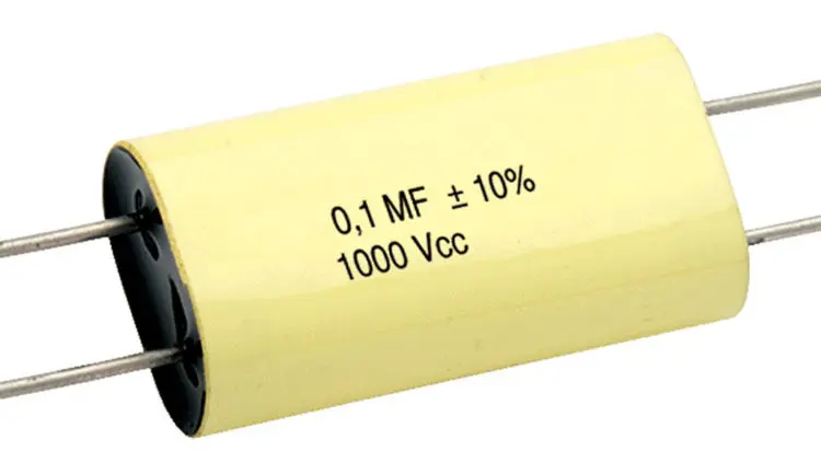
Film and Foil Organic Dielectric Capacitors PS,PPS,PTFE,PSU

binder Unveils Quick Lock Ruggedized Power Bayonet

binder Unveils Quick Lock Ruggedized Power Bayonet

Feedback from Connector Failure Analysis

Improving High Voltage Power Modules with new Silicon Snubber Capacitor Technology  

Skeleton Unveils the Leipzig Supercapacitor Factory

Skeleton Unveils the Leipzig Supercapacitor Factory

Snubber Capacitors in Power Electronics

Snubber Capacitors in Power Electronics

TAIYO YUDEN Expands Lineup of Multilayer Metal Power Inductors

TAIYO YUDEN Expands Lineup of Multilayer Metal Power Inductors

Bourns Releases New High Energy Gas Discharge Tubes

Bourns Releases New High Energy Gas Discharge Tubes

Würth Elektronik Extends its Application and Industry Guide for Easy Navigation to Suitable Circuits and Components

Würth Elektronik Extends its Application and Industry Guide for Easy Navigation to Suitable Circuits and Components

Designing a Small Integrated 500W LLC Transformer

Designing a Small Integrated 500W LLC Transformer

Connector Raw Material Costs Decreased 6.9 Percent in Q2 2023

Connector Raw Material Costs Decreased 6.9 Percent in Q2 2023

  • Home
  • ABC of CLR
    • All
    • ABC of Capacitors
    • ABC of Inductors
    • ABC of Resistors
    • Mounting Guidelines

    RF Inductors and Filters

    Power transformers

    Telecom transformers

    LAN transformers

    Transformer Calculation and Applications

    Power Inductors 2 (cont.)

    Power inductors

    Current compensated chokes

    Coil with ferrite

    Trending Tags

      • ABC of Capacitors
      • ABC of Inductors
      • ABC of Resistors
      • Mounting Guidelines
    • e-Symposium
    • EPCI Membership
    • About
    No Result
    View All Result
    European Passive Components Institute
    • Home
    • ABC of CLR
      • All
      • ABC of Capacitors
      • ABC of Inductors
      • ABC of Resistors
      • Mounting Guidelines

      RF Inductors and Filters

      Power transformers

      Telecom transformers

      LAN transformers

      Transformer Calculation and Applications

      Power Inductors 2 (cont.)

      Power inductors

      Current compensated chokes

      Coil with ferrite

      Trending Tags

        • ABC of Capacitors
        • ABC of Inductors
        • ABC of Resistors
        • Mounting Guidelines
      • e-Symposium
      • EPCI Membership
      • About
      No Result
      View All Result
      European Passive Components Institute
      No Result
      View All Result
      Home ABC of CLR ABC of Capacitors

      Film and Foil Organic Dielectric Capacitors PS,PPS,PTFE,PSU

      January 21, 2022
      Reading Time: 5 mins read
      66 2
      A A

      C 2.6 POLYSTYRENE (PS) and POLYPHENYLENE SULFIDE (PPS)

      Polystyrene (PS) represents a non-polar dielectric material that just as polycarbonate to a great extent has been replaced by polypropylene. The availability is strongly limited due to ceased production.

      Polyphenylene Sulfide or simply PPS has come to stay mainly because of its relatively high temperature resistance which has allowed SMD manufacture.

      C 2.6.1  General comments to PS

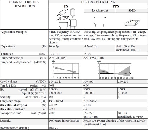
      εr ≈  2.4. Max. temp.+70°C (possibly +85°C). Smallest film thickness 4 μm (0.16 mils). Except for metal foils often double metallized plastic foils are used.

      Advantages

      • Very low losses; 0.01% at room ambient and 1 kHz.
      • Very high IR; RC 200 000 s. Actually it’s more exterior factors that determines the IR than the material itself.
      • Dielectric absorption 0.02%.
      • Stability ΔC/C, max ± 0.5%.

      Disadvantages

      • Can not be metallized due to high carbon deposits and too little oxygen available at a self-healing breakdown.
      • Chemically sensitive film.
      • Availability limited due to ceased production.

      C 2.6.2    Temperature and frequency dependencies for PS
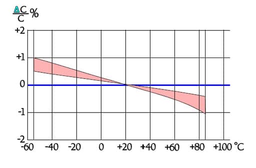
      Figure C2-57. Capacitance versus temperature for PS capacitors.
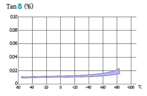
      Figure C2-58. Tan versus temperature for PS.
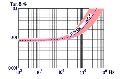
      Figure C2-59. Typical curve range for Tanδ versus frequency for PS.
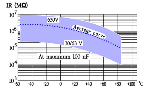
      Figure C2-60. Typical curve range for IR versus temperature in PS capacitors, when C ≤0.1μF.

      C 2.6.3  General comments to PPS

      Foil types exist but metallized design is a rule. If nothing else is said metallized film applies.

      εr ≈3.0. Max. temp.+140 °C; most manufacturers recommend maximum +125 °C. Dielectric absorption ≈ 0.1%.

      Smallest film thickness is 1.2 μm (0.05 mils) but former quality problems with the thinnest film may give cause for stronger derating of the lowest rated voltage. However, the supply of film is stabilized thus indicating an established demand..

      The film is used in capacitors both for lead mount and SMD. Existing chip types are made in a stacked design.

      C 2.6.4    Temperature and frequency dependencies for PPS
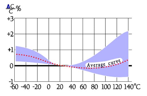
      Figure C2-61. Typical curve range for capacitance versus temperature in PPS capacitors.
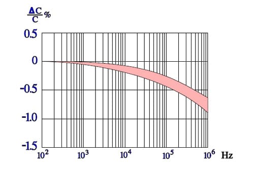
      Figure C2-62.  Typical curve range for capacitance versus frequency in PPS capacitors.
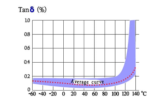
      Figure C2-63.   Typical curve range for Tanδ versus temperature in PPS capacitors.
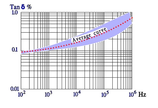
      Figure C2-64.   Typical curve range for Tan versus frequency in PPS capacitors.
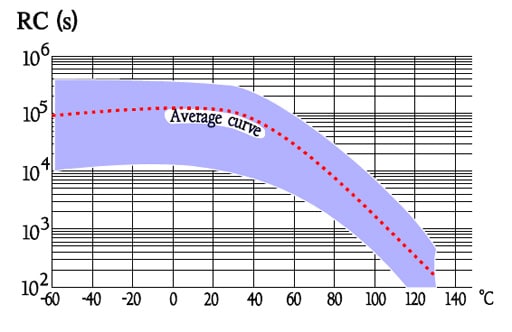
      Figure C2-65.   Typical curve range for IR versus temperature in PPS capacitors.

      Table C2-7.  POLYSTYRENE (PS) and  POLYPHENYLENE SULFIDE (PPS)
      C 2.7 OTHER PLASTIC FILMS

      Following selection contains plastic films for special purposes.

      C 4.7.1   Teflon (PTFE)

      Teflon exists both in metallized and foil design. The greatest advantage of the film is its temperature resistance. The price, on the other hand, is high which gives cause for exclusive hermetic designs.

      • Capacitance 470pF….4.3μF.
      • Tolerance ±0.25….±20%.
      • Temperature range -65/+200°C.
      • TC -200…+50ppm/°C.
      • Rated voltage 50…600 V DC.
      • Tanδ , @ 1kHz, 20°C, ≤0.1%.
      • IR, @ 20°C, foil ≥500GΩ/ ≥100 000s,
      • IR, @ 20°C, metallized film 50GΩ/ 10 000s.
      • Stability  ΔC/C max -1%.
      • εr ≈ 2.2.
      • Dielectric absorption  ≤0.02%.
      • Recommended derating 0.6xVR.

      C 4.7.2  Polysulfone (PSU)

      Polysulfone capacitors belong to the same price group as the one of teflon. They are used only in special applications where high temperature capabilities together with excellent characteristics are of vital importance. The capacitors have been manufactured only in hermetic design and with foil electrodes.

      • Capacitance 1nF….22μF.
      • Tolerance ±0.25….±10%.
      • Temperature range -65/+150°C.
      • TC -200…+50ppm/°C.
      • Rated voltage 50…400 V DC.
      • Tanδ , @ 1kHz, 20°C, ≤0.15%.
      • IR, @ 20°C, foil ≥1000GΩ
      • εr ≈ 3.2.
      • Dielectric absorption  ≤0.2%.
      • Recommended derating 0.6xVR.

      ABC of CLR: Chapter C Capacitors

      Film and Foil Organic Capacitors PS,PPS,PTFE,PSU

      EPCI licenced content by:
      [1] EPCI European Passive Components Institute experts original articles
      [2] CLR Passive Components Handbook by P-O.Fagerholt*
      *used under EPCI copyright from CTI Corporation, USA 

      Creative Commons License

      This page content is licensed under a Creative Commons Attribution-ShareAlike 4.0 International License.

      see the previous page:Film and Foil Organic Capacitors PP and PC

      < Page 10 >

      see the next page:Film and Foil Organic Capacitors Comparison Charts
      Previous Post

      Film and Foil Organic Dielectric Capacitors PP and PC

      Next Post

      Film and Foil Organic Dielectric Capacitors Comparison Charts
      Related Posts

      ABC of CLR

      RF Inductors and Filters

      ABC of CLR

      Power transformers

      ABC of CLR

      Telecom transformers

      Categories

      • ABC of CLR
        • ABC of Capacitors
        • ABC of Inductors
        • ABC of Resistors
        • Mounting Guidelines
      • e-Symposium
        • ESA SPCD
        • PCNS
      • EPCI news
      • Market Insights
      • news collection

      Popular Posts

      • Transformer: Parasitic parameters and equivalent circuit

        1434 shares
        Share 574 Tweet 359
      • Transformer Calculation and Applications

        715 shares
        Share 286 Tweet 179
      • Introduction to Ceramic Capacitors

        521 shares
        Share 208 Tweet 130
      • Simulation with LTspice

        499 shares
        Share 200 Tweet 125
      • Dielectric Insulation Resistance, Capacitor DCL Leakage Current and Voltage Breakdown

        436 shares
        Share 174 Tweet 109

      Subscribe to Blog via Email

      Enter your email address to subscribe to this blog and receive notifications of new posts by email.

      © 2023 European Passive Components Institute

      No Result
      View All Result
      • Home
      • ABC of CLR
        • ABC of Capacitors
        • ABC of Inductors
        • ABC of Resistors
        • Mounting Guidelines
      • e-Symposium
      • EPCI Membership
      • About

      Welcome Back!

      Login to your account below

      Forgotten Password?

      Retrieve your password

      Please enter your username or email address to reset your password.

      Log In
      This website uses cookies. By continuing to use this website you are giving consent to cookies being used. Visit our Privacy and Cookie Policy.