


")


C 2.12 OTHER INORGANIC DIELECTRICS
C 2.12.1 Class 3 ceramics
The headlined type of ceramic capacitor are also called barrier layer capacitor. It consists of sintered granules of titanium oxides with semiconductor properties. On the surface of every granule there is created a capacitive barrier layer zone. The sum of all small capacitance elements gives a high total capacitance. The dielectric constant will be correspondingly high – εr ≤ 100 000 – but the dielectric withstanding voltage (and rated voltage) as well as the IR will be low. The temperature dependence is very high and the stability poor.
Thus Class 3 ceramics are of a very small importance in professional electronics. Hence we confine ourselves just with mentioning the occurrence.
C 2.12.2 Glass capacitors
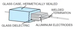
The one in all respects most environmentally resistant capacitor we know is the glass capacitor. Except for common environments the capacitor also will stand high nuclear radiation doses and strong neutron radiation. It is specified in US MIL-C-11272 and –23269. The capacitance range is limited compare to other technologies to tenth of nanofarads. The capacitor is, just as the MLCC, manufactured in a stacked form. Both the dielectric and encapsulation consist of glass that constitutes a homogeneous and extremely resistive product in all environments.
The electrodes most often consist of aluminum foils that are folded over the edges of the end surfaces and are welded to the connecting leads. A relatively thick dielectric – at least 50 µm – and a thick encapsulation makes together with the aluminum foils the capacitor bulky. On the other hand the Al foils permit high surge currents. The dielectric absorption of older production was stated to approximately 0.5%, while testing of recent manufacture accounts for 0.01 %. The most common failure usually is defective weld joints between Al foils and leads. High pulse currents then burn the weak joints thus causing an open-circuit. The failure rate in general increases with the proportions λ120° : λ25° ≈ 50 : 1.
Summary of glass capacitors
- very high stability, no corrosion or degradation, no microfractures, delaminations …
- hermetically axial case practically immune to severe environmental effects such as shock, vibration, radiation resistance, moisture, salt spray, and solder heat.
- zero aging rate, high Q factor, large RF Current Capability, no piezoelectric noise, low dielectric absorption, ±5ppm temperature coefficient retraceability, high breakdown voltage, zero voltage coefficient, up to -75°C – +200°C
- pF to hundreds / th. pF, several hundreds V
C 2.12.3 Mica capacitors
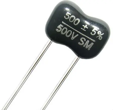
Previously MICA capacitors have due to their stability and their good HF characteristics been dominating for filter purposes. Today there are plastic film capacitors that in many respects are more favorable. What still makes the mica capacitor interesting is its stability, the small tolerances and the temperature range (-55/+125 and up to 200°C). Mica is a mineral that for capacitor purposes is mined dominantly in India. Mica has a high voltage strength and low losses. The capacitors are manufactures in a stacked form, either with metal foil electrodes (stacked mica), or with electrodes consisting of a screen printed silver oxide paste that under reduction to silver is burnt to the mica surface, so called silvered mica.
The stacked mica can, among other things, stand higher currents and are more used in power electronics. We only mention their occurrence and will not deal with the subject any further. The silvered mica capacitors that are most common normally can stand currents only in the mA range but there exist special designs for stronger currents. Silvered mica are also produced as chips. There are examples that show that the capability to stand power sometimes is better than that of ceramic Class 1 chips.
A special variant of mica capacitors is the mica paper type. Small mica scales are treated approximately like paper pulp and is transferred to sheets and either wound with aluminum foils or stacked with electrodes. The result will be a kind of mica capacitor with relatively high losses (similar to polyester and paper) and in other respects equivalent to the conventional mica. Also this type belongs more to the power electronics and will not be treated further in this context. The connection to the silvered mica electrodes is made at the edge of the end surfaces by special foil sheets, usually silver.
The silvered mica packet then is pressed together, the silver foil sheets are folded and soldered to the connecting leads whereupon the packet is supplied with fixing metal clamps. The stack is vacuum impregnated, usually with epoxy. Because the silver electrodes are extremely apt to migration in moisture the capacitor has to be encapsulated. Either it is molded in plastic or dipped in some kind of phenolic lacquer. The more layers the better vapor barrier. For professional applications there should be at least four layers of lacquer. The pressure clamps lead at temperature changes to traces of capacitance hysteresis. When we return to the starting temperature a certain ∆C appears that due to the TCE of the clamps cause an incomplete mechanical pressing together to the initial pressure.
Measurement frequencies:
- C ≤ 1000 pF Measurement frequency 1 MHz.
- C > 1000 pF Measurement frequency 1 kHz.
MICA capacitors summary
- Mica minerals are very stable electrically, chemically and mechanically. Because of its specific crystalline structure binding, it has a typical layered structure. This makes it possible to manufacture thin sheets in the order of 0.025-0.125 mm
- high thermal stability performance at temperatures of 175°C+
- high power applications requiring low inductance at high frequencies, temperatures up to +200°C, and voltages up to 1,000Vdc.
- axial leaded with voltage ratings up to 5KVdc, capacitance ratings as high as 3.0µF, and a temperature rating of +175°C.
- hermetic metal or glass bead seal in radial and axial mounting options; the rated voltage range is 63Vdc – 250Vdc, and the operating temperature range -55°C – +200°C. These capacitors are designed for extreme temperature applications such as oil/gas exploration and high temperature engines.
C 2.12.4. Air/Vacuum capacitors
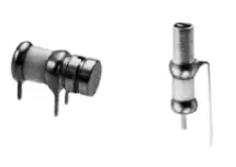
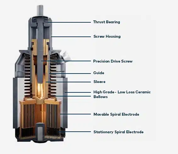
Very specific group of capacitors are air and vacuum capacitors. Relative permittivity dielectric constant is close to 1 as per its definition, thus capacitors are large in size. Nevertheless, its losses are low under high power load. These capacitors are used specifically for RF applications from VHF to microwave frequencies in power broadcasting as trimmer capacitors etc.
Air/Vacuum capacitors summary
- Air trimmer capacitors
- Specifically for RF applications, VHF through microwave
- High Q and temperature stability
- Vacuum – high power RF – broadcasting, networks, tenth of kV, hundreds pF
COMPARISON

Table C2-14. GLASS / MICA
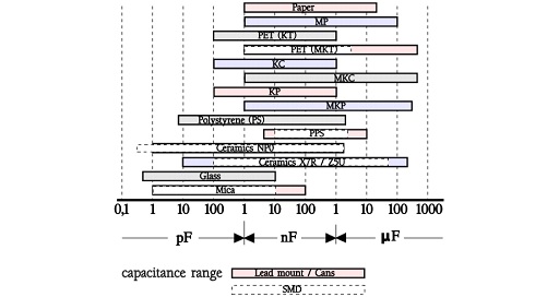
C 2.13 COMPARISON DIAGRAMS, ELECTROSTATIC CAPACITORS

featured image: High Temp Mica Capacitor; credit: Green Tech
ABC of CLR: Chapter C Capacitors
OTHER INORGANIC DIELECTRICS
EPCI licenced content by:
[1] EPCI European Passive Components Institute experts original articles
[2] CLR Passive Components Handbook by P-O.Fagerholt*
*used under EPCI copyright from CTI Corporation, USA

This page content is licensed under a Creative Commons Attribution-Share Alike 4.0 International License.
see the previous page:
< Page 15 >
see the next page:


