


")


C 3.5 SOLID AL ELECTROLYTICS with CONDUCTIVE POLYMER or TCNQ SALT
C 3.5.1 Polymer electrolyte
Other variant of a solid electrolyte is conductive polymer electrolyte. The aluminum oxide on an etched and formed foil is covered with an electrically very conductive and doped polymer as previously shown in Figure C3-7. The polymer can withstand temperatures up to +105 °C. The ESR of the capacitor is several ten powers better than that of the wet electrolytic types. Its temperature dependence is negligible, but the frequency dependence is more pronounced (Figure C3-41).
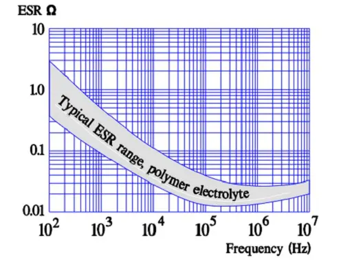
Figure C3-41. Typical ESR versus frequency in polymer electrolytes.
The polymer electrolytic capacitor is manufactured in a can or a chip construction with ESR range from 4.5mΩ to 70mΩ, voltage range 2 V to 16 V and capacitance from μF to hundreds of μF. Recommended derating is to use ≤ 80% of VR. The capacitor must not be subjected to any reverse voltage. In case of a short-circuit the local heat generation from the current in the failure spot will be so high that the polymer either will oxidize or will be de-doped and thus creates an insulating “patch” over the failure area. Thus, the capacitor self-heals.
An advantageous chip design is the flat stacked type shown in Figure C3-42. It consists of stacked aluminum plates that have been etched and supplied with an anodic oxidation. The tunnel like structure is covered with a polymerized thin conductive film. Between this film and the following silver paint is added a graphite layer serving as a buffer between the polymer and the silver coating.
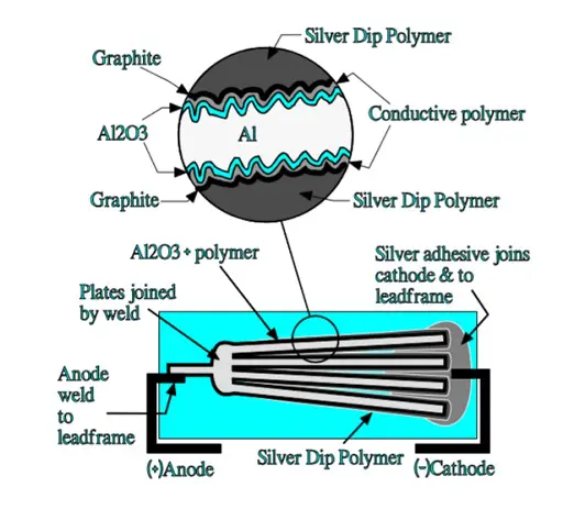
Figure C3-42. Schematic of a polymeric aluminum electrolytic capacitor.
The aluminum plates are dipped in a silver epoxy that covers the polymer and graphite surface and fills up the spongy structure of the aluminum plates. The device is then molded in the same plastic epoxy as the one used in solid tantalum SMDs. This construction has an excellent volumetric efficiency. There is a significant difference between this construction and that of a solid sintered tantalum capacitor.
In the latter case the current has to pass “horizontally” through the MnO2 cover to charge the inner capacitive elements in the porous tantalum pellet. In the stacked aluminum construction the current passes “vertically” through the silver, carbon and polymer layers to the inner capacitive elements in the etched tunnels as shown in Figure C3-43.
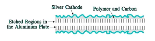
Figure C3-43. Schematic of an etched aluminum plate with additional cathode layers.
The vertical current paths means a considerably reduced ESR. Such capacitors are capable of a single-digit ESR in the 100 kHz region.
The polymer capacitor is well established and has its greatest advantages in smoothing and noise reduction applications. For high reliability applications, however, its capability in high-shock mechanical environments must be evaluated.
Hybrid Aluminum Electrolytic Capacitors
There also exists a hybrid version of the polymeric style. It has a construction of principle as shown in Figure C3-44. The combination of a liquid electrolyte and a polymer reduces the ESR at the same time as the self-healing properties are retained due to the ion movability.
This type is growing presence on the market as Al can construction (SMD variant is also available) due to its improved robustness to IR reflow mounting conditions compare to Al pure polymer electrolyte solution.
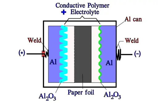
Figure C3-44. Schematic of a hybrid Al electrolytic capacitor with aluminum can and cathode foil.
C 3.5.2 TCNQ salt
Like the polymer electrolyte the semiconducting organic salt TCNQ has also been available on the market for a number of years. The winding is impregnated at a relatively high temperature with melted salt that at cooling is transformed into a solid state. Its ESR is better than that of wet electrolyte but somewhat poorer than that of the polymer electrolyte. The temperature dependence of the ESR is negligible but its frequency dependence more pronounced (Figure C3-45). Note its similarity with the polymer electrolytic.
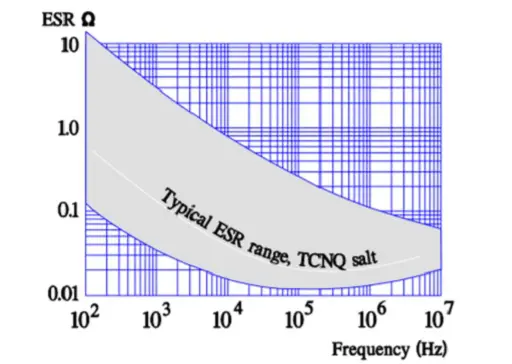
Figure C3-45. Typical ESR versus frequency in TCNQ electrolytes.
This capacitor is sensitive both to mechanical shocks and ESD. It can endure certain vibration environments. Immediately after soldering it should not be subjected to handling due to the heat influence on the structural strength of the electrolyte/ dielectric system. The highest rated voltage should be derated linearly from 25 V at 85 °C to 20 V at 105 °C.
- Capacitance range 0.1⋅⋅⋅680 µF
- Temperature range -55/+105°C
- Maximum rated voltage 30 V DC
- ESR, frequency and temperature dependence ≈ that of the polymer capacitor.
Self-healing may occur at short-circuiting. In the failure spot the short-circuit current generates so much heat that the salt decomposes or disappears and thus creates a local insulation area. The capacitor must not be subjected to surge currents or to any overvoltage. Prolonged load at high temperatures will lead to capacitance decrease or in the worst case to open mode. TCNQ salt may also present some risk to environment and ROHS regulation due to presence of cyanide salts. Thus polymer/hybrid types are the main growing aluminum electrolytic capacitor technologies at present stage.
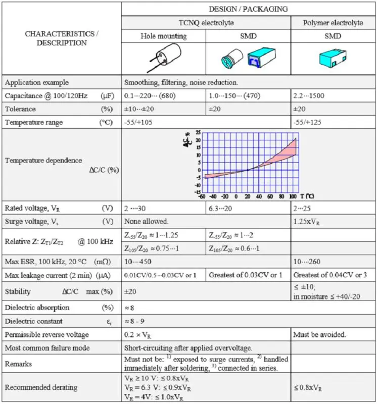
Table C 3-8. SOLID AL ELECTROLYTICS, POLARIZED, with CONDUCTIVE POLYMER or TCNQ SALT
ABC of CLR: Chapter C Capacitors
Solid Al Electrolytics with Conductive Polymer or TCNQ Salt
EPCI licenced content by:
[1] EPCI European Passive Components Institute experts original articles
[2] CLR Passive Components Handbook by P-O.Fagerholt*
*used under EPCI copyright from CTI Corporation, USA
![]()
This page content is licensed under a Creative Commons Attribution-Share Alike 4.0 International License.
see the previous page:
Solid Aluminum Electrolytics with Manganese Dioxide (obsolete)
< Page 20 >
see the next page:
Solid Sintered Tantalums with Manganese Dioxide and Polymer Electrolyte


