L.1.8 Differentiating EMC ferrite ↔ inductor
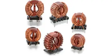
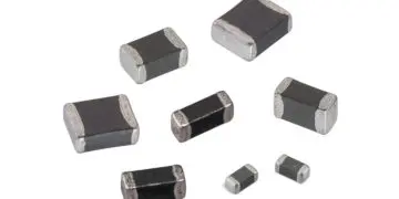
The terminology used in this handbook clearly distinguishes between inductors and EMC ferrites in regard to the quality of the inductor:
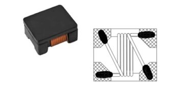
EMC ferrites are based on Ni-Zn materials. This material has good quality factors (Q < 3) above approx. 20 MHz – i.e. trimmed for high losses. These originate in the core material and serve to absorb EMC interference. The inductance of these components is purposely kept low.
Inductors however should show high quality factors, i.e. operate as loss-free as possible and buffer energy in the magnetic field. Also, they require stable inductance values over a wide frequency range. The distinction emphasized is reflected in the layout of the relevant manufacturer catalogue.
1.9 Functionality of a transformer
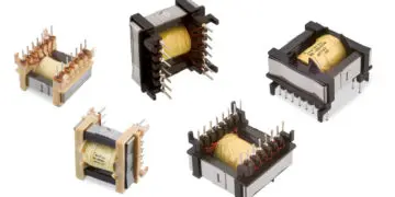
A transformer consists of at least two windings, with the winding turns NP on the primary side and NS on the secondary side. For the sake of simplicity, we will look at
an ideal transformer with a turns ratio of 1 : 1.
In a first step, we will look at a transformer with an open secondary winding NS (Figure 1.32). A UP voltage pulse is created at winding NP. Due to the inductance of the
winding, this pulse generates a linearly progressive current IP. The following applies:

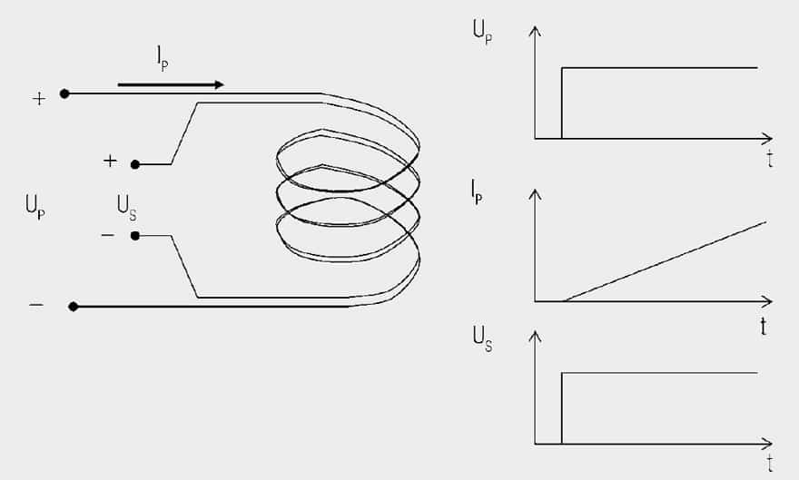
Fig. 1.32: Principle of a transformer with zero load. This ideal transformer is wound as a bifilar so as to ignore parasitic effects.
Winding NS also wraps around this magnetic flux. Changing the magnetic flux creates voltage.

If you solve both equations after changing the voltage and then equate them, you will get the following for the voltage transformation:

Current does not flow in winding NS because the winding is open. If we now connect winding NS to a load resistor RL (Figure 1.33), the voltage induced in NS generates a current flow through the load resistor:
 Fig. 1.33: The same transformer but with a load
The primary current now consists of the transformed secondary current and the linearly progressive magnetisation current that is already available without load.
 IS* Secondary current transformed on the primary side
As no power can be generated, the transformed power is the same as the primary power put into the system. If the magnetisation current is disregarded, the following applies:

Currents are thus transformed in the reversed direction as voltage. The following also applies:

Resistances are thus transformed with the transformation ratio squared. This also applies to inductances, capacitances and impedances. So the magnetising current is not transferred to the secondary side. It is required to generate the magnetic field. The aim of the transformer design must therefore be to keep the magnetizing current as small as possible.
There are two possibilities here:
- Insertion of a highly permeable core to increase the primary inductance. This causes the magnetizing current to rise less steeply and is therefore smaller (Figure 1.34).

Fig. 1.34: Magnetizing current of a transformer with and without a highly permeable core
- Shorter voltage pulses with higher frequency are generated, as the rise in current stops at the end of the voltage pulse and starts again at the original point for the
next pulse (Figure 1.35).

Fig. 1.35: Magnetizing current for a transformer at different driving frequencies
Parasitic effects
In reality, there are other factors that affect the behavior of transformers. The most important ones are:
- Leakage inductance
- Coupling capacitance (capacitance between windings)
- Winding capacitance (capacitance within a winding)
Leakage inductance
Looking at two windings, we see that the entire flux is not coupled to the other winding. A part of the streamlines of the magnetic field closes outside of the other winding. This part of the inductance is called “leakage inductance.” To understand how to minimize leakage inductance, you must know the parameters that influence it.
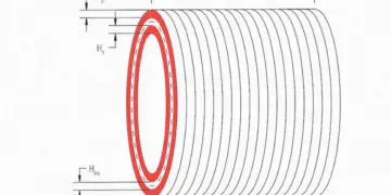
If you look at a long concentric coil (Figure 1.36), its inductance results from:

lW Length of the coil
N Winding turns
A Cross section of the coil
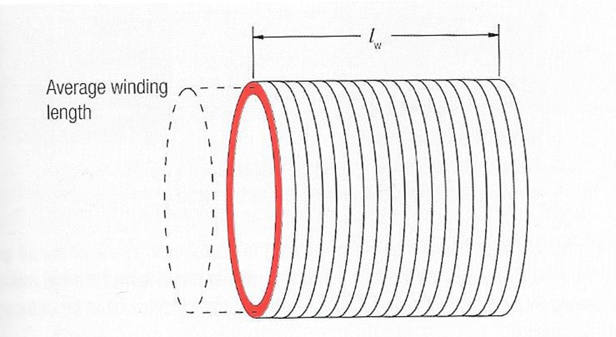
Fig. 1.36: Long solenoid
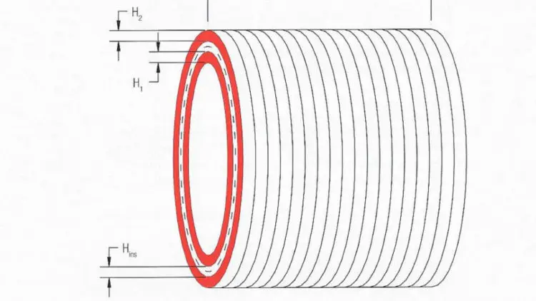
If a second winding is wound on top of it (Figure 1.37), the leakage inductance results from (1.48)

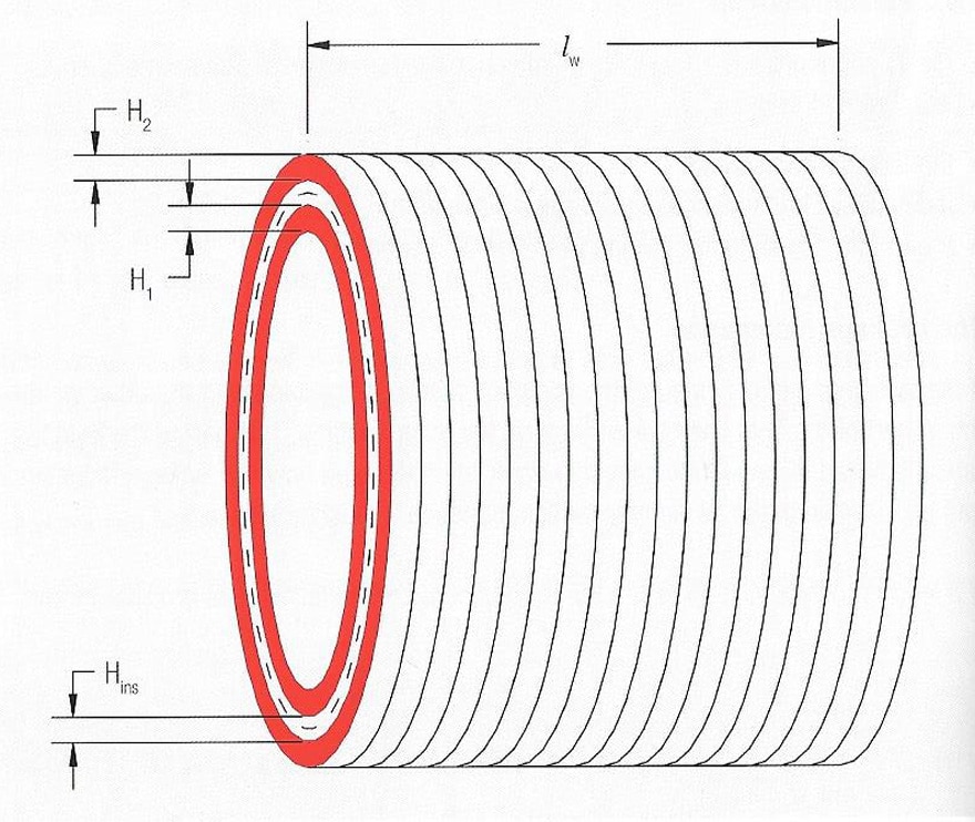
Fig. 1.37: Long solenoid with second winding
Where A here is the surface between the two windings. It can be calculated using:
 MLT Mean length of turn
Hins Distance between the windings (isolation)
H1, H2 Winding height of windings 1 and 2
The leakage inductance is thus independent of core material and air gap. To minimize leakage inductance you must either increase the length of the coil (broad windings) or reduce the distance between the windings (e.g. bifilar wind).
Figure 1.38 shows various more or less ideal winding constructions. With existing geometry the most commonly used means is a sandwich construction (Figure 1.38d), in which the secondary winding is wound between the primary winding that is divided into two halves. This doubles the length of the winding.
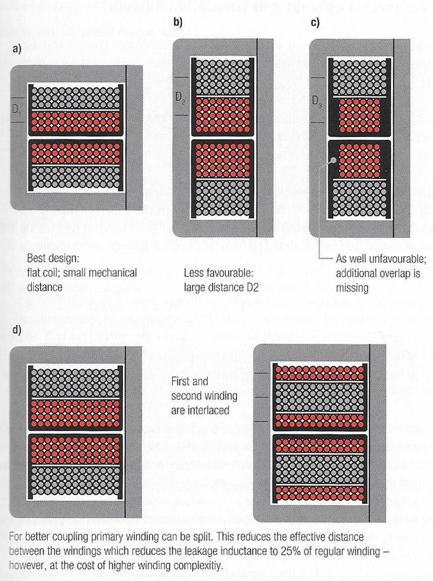
Fig. 1.38: Different winding structures
Coupling capacitance
You can picture the coupling capacitance between the two windings as plate capacitor between the two windings. From this it follows that you can reduce this capacitance either by increasing the distance or reducing the surface. Both directly increase leakage inductance.
Winding capacitance
Each winding builds up winding capacitance because they are isolated from each other and rest on different potential. This capacitance increases with the number of layers that are required within a winding. It can be reduced by means of various winding technologies, e.g. Z-wind (wire is returned after each layer).
ABC of CLR: Chapter L Inductors
Functionality of Transformer
EPCI licensed content by: Würth Elektronik eiSos, Trilogy of Magnetics, handbook printouts can be ordered here.
This page content is licensed under a Creative Commons Attribution-ShareAlike 4.0 International License.
see the previous page:
< Page 6 >
see the next page:
