• Latest
  • Trending
Magnetic Induction, Magnetic Flux and Faraday’s Law

Magnetic Induction, Magnetic Flux and Faraday’s Law

Modelithics Releases Components Library v25.0 for Keysight 

Modelithics Releases Components Library v25.0 for Keysight 

How to design a 60W Flyback Transformer

How to design a 60W Flyback Transformer

Researchers Present Hybrid Supercapacitor Zn-Ion Microcapacitors

Researchers Present Hybrid Supercapacitor Zn-Ion Microcapacitors

Murata Releases 008004 High-Frequency SMD Chip Inductor

Murata Releases 008004 High-Frequency SMD Chip Inductor

Wk 19 Electronics Supply Chain Digest

Wk 19 Electronics Supply Chain Digest

Bourns Extends Rotational Life Option for its Guitar Potentiometer

Bourns Extends Rotational Life Option for its Guitar Potentiometer

Modeling and Simulation of Leakage Inductance

Modeling and Simulation of Leakage Inductance

Power Inductor Considerations for AI High Power Computing – Vishay Video

Power Inductor Considerations for AI High Power Computing – Vishay Video

TAIYO YUDEN Releases Compact SMD Power Inductors for Automotive Application

TAIYO YUDEN Releases Compact SMD Power Inductors for Automotive Application

Fischer Releases High Vibration Robust Ratchet Locking USB-C Connector System

Fischer Releases High Vibration Robust Ratchet Locking USB-C Connector System

  • Home
  • ABC of CLR
    • All
    • ABC of Capacitors
    • ABC of Inductors
    • ABC of Resistors
    • Mounting Guidelines
    RF Inductors and Filters

    RF Inductors and Filters

    Power transformers

    Power transformers

    Telecom transformers

    Telecom transformers

    LAN transformers

    LAN transformers

    Transformer Calculation and Applications

    Transformer Calculation and Applications

    Power Inductors 2 (cont.)

    Power Inductors 2 (cont.)

    Power inductors

    Power inductors

    Current compensated chokes

    Current compensated chokes

    Coil with ferrite

    Coil with ferrite

    • ABC of Capacitors
    • ABC of Inductors
    • ABC of Resistors
    • Mounting Guidelines
  • e-Symposium
  • EPCI Membership
  • About
No Result
View All Result
European Passive Components Institute
  • Home
  • ABC of CLR
    • All
    • ABC of Capacitors
    • ABC of Inductors
    • ABC of Resistors
    • Mounting Guidelines
    RF Inductors and Filters

    RF Inductors and Filters

    Power transformers

    Power transformers

    Telecom transformers

    Telecom transformers

    LAN transformers

    LAN transformers

    Transformer Calculation and Applications

    Transformer Calculation and Applications

    Power Inductors 2 (cont.)

    Power Inductors 2 (cont.)

    Power inductors

    Power inductors

    Current compensated chokes

    Current compensated chokes

    Coil with ferrite

    Coil with ferrite

    • ABC of Capacitors
    • ABC of Inductors
    • ABC of Resistors
    • Mounting Guidelines
  • e-Symposium
  • EPCI Membership
  • About
No Result
View All Result
EPCI
No Result
View All Result
Home ABC of CLR

Magnetic Induction, Magnetic Flux and Faraday’s Law

February 10, 2022
Reading Time: 4 mins read
A A
Magnetic Induction, Magnetic Flux and Faraday’s Law

L.1.2 Magnetic induction B

A potential is induced in a conductor loop if the magnetic field passing through the conductor loop changes with time.

Featured Image Fig. 1.10: Experimental configuration for magnetic induction

The surge in potential over the area of the loop is known as the magnetic induction B. Like the magnetic field strength, the magnetic induction B is a vector quantity.

The following relationship applies for the magnetic induction B:


The magnetic induction (B) is the quotient of the induced potential surge:

and the product of the winding turns (N) and the windings area (A) of the induction coil.

The unit of magnetic induction (B) is the Tesla (T) = Vs/m2.

The magnetic induction B and the field strength H are proportional to one another.

The constant of proportionality is the magnetic field constant (μ0), given by experimental measurement.


In vacuum and also with sufficient accuracy for air, this leads to:

The magnetic induction (BL) in air for the above example is given by:

L.1.3 Magnetic flux F

The magnetic flux (F) is the scalar product of the magnetic flux density (B) and the area vector (dA).


If (B) passes perpendicular through the area and the field is homogenous:


The unit of magnetic flux (F) is the same as that of the voltage surge (Vs) (Voltsecond) or Weber (Wb).

L.1.4 Faraday’s law

Up until now we have considered static magnetic fields. If the magnetic flux changes with time, a voltage U is induced (Faraday’s law).

U = induced voltage
t = time

The polarity of the voltage is such that a current is generated on closing a circuit whose induced magnetic field opposes the original magnetic flux, i.e. it tends to reduce the magnetic field (Lenz’s rule – Figure 1.11).

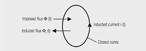
Fig. 1.11: Representation of Lenz’s rule. The imposed magnetic field induces a current in the direction such that its induced magnetic field opposes the imposed field

Taking a winding with N turns, Faraday’s law can be expressed in the following form.

A = cross section of the coil
l = length of the coil or of the magnetic circuit
I = current through the coil
L = inductance of the coil [H(enry) = Vs/A]

So the inductance limits the change in current once a voltage is applied. It can be calculated from the coil data:

AL = AL value; mostly in nH/N2

The energy stored in the magnetic field is subject to the following relationships:


The energy stored in the volume V is composed of both the magnetic field strength H and the magnet flux density B. For transformers and chokes with ferromagnetic cores, the flux density is limited by saturation (see chapter I/1.5) and is constant throughout the magnetic circuit. If an air gap is introduced (material with permeability μ~1), the field strength is highest in this air gap with H = B/μ. It follows that the energy density is highest in the air gap. One also speaks of the energy being stored in the air gap.

Comparing magnetic fields with electrical fields, analogies emerge between certain parameters. These are summarised in Table 1.1:

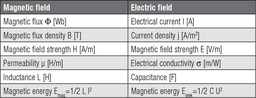
Tab. 1.1: Analogies between magnetic and electric fields


ABC of CLR: Chapter L Inductors

EPCI licensed content by: Würth Elektronik eiSos, Trilogy of Magnetics, handbook printouts can be ordered here.

Creative Commons License

This page content is licensed under a Creative Commons Attribution-ShareAlike 4.0 International License.

see the previous page:

Inductors – Basic Principles, Ampère’s Law and Magnetic Fields Strength

< Page 2 >

see the next page:

Core Materials and Their Losses

Previous Post

Losses (ESR, IMP, DF, Q)

Next Post

Core Materials and Their Losses

Related Posts

RF Inductors and Filters
ABC of CLR

RF Inductors and Filters

Power transformers
ABC of CLR

Power transformers

Telecom transformers
ABC of CLR

Telecom transformers

Categories

  • ABC of CLR
    • ABC of Capacitors
    • ABC of Inductors
    • ABC of Resistors
    • Mounting Guidelines
  • e-Symposium
    • ESA SPCD
    • PCNS
  • EPCI news
  • Market Insights
  • news collection
  • Transformer: Parasitic parameters and equivalent circuit

    Transformer: Parasitic parameters and equivalent circuit

    0 shares
    Share 0 Tweet 0
  • Transformer Calculation and Applications

    0 shares
    Share 0 Tweet 0
  • Introduction to Ceramic Capacitors

    0 shares
    Share 0 Tweet 0
  • Simulation with LTspice

    0 shares
    Share 0 Tweet 0
  • Dielectric Insulation Resistance, Capacitor DCL Leakage Current and Voltage Breakdown

    0 shares
    Share 0 Tweet 0

© 2024 European Passive Components Institute

No Result
View All Result
  • Home
  • ABC of CLR
    • ABC of Capacitors
    • ABC of Inductors
    • ABC of Resistors
    • Mounting Guidelines
  • e-Symposium
  • EPCI Membership
  • About
This website uses cookies. By continuing to use this website you are giving consent to cookies being used. Visit our Privacy and Cookie Policy.
Go to mobile version