


")


R 5.1 NTC THERMISTORS
In this section we shall describe some non-linear resistor styles, meaning that they don’t follow Ohm’s law. Simplified, the resistor material consists of doped granule compounds containing various oxides that by means of binders have been pressed to a desired shape and then sintered. The terminals either are inserted into the resistor body or soldered to metallized surfaces. There are a number of encapsulation types.
R 5.1.1 Designs
NTC thermistors exist as rods, discs, beads covered with lacquer, epoxy, glaze or melted glass and as SMDs.
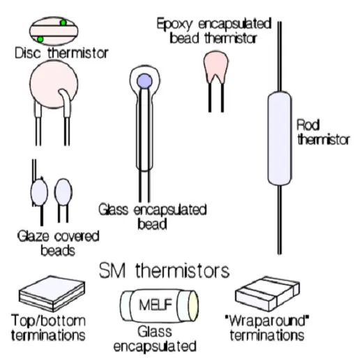
Figure R5-1. Thermistor design examples.
SMD thermistors in low ohmic designs are made with a number of internal electrodes as shown in Figure R5-2. The reduced resistance is achieved by a construction that connect “resistor elements” in parallel inside the thermistor body.
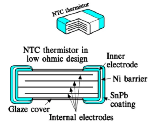
Figure R5-2. Construction of a low ohmic chip thermistor.
R 5.1.2. Temperature dependence and tolerances
NTC stands for negative TCR (Negative Temperature Coefficient). The temperature dependence is strong and exponential and follows the formula
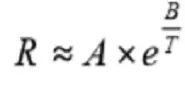
The material constant A determines the resistance and B its temperature dependence, i.e. the slope of the resistance – temperature curve. T means the temperature in Kelvin (°C + 273). If we apply the formula [R5-1] on a reference temperature T0 and a general temperature T and combine the two expressions we obtain the formula
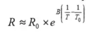
The constant B generally is determined by measurements at 25 and 50 °C. It usually has values between 2500 and 5000. The value varies a little with temperature. Hence the ≈ symbol in the formulas. The thermistor material shrinks strongly during the sintering process which causes great difficulties keeping the tolerances on both the R25 and the B value within specified limits. The B value is stated with tolerances that usually are 5 %. The reference value R0 relates to 20 or 25 °C and has tolerances of 5, 10 or 20 %. However, by sawing already sintered chips to close dimensions one increases the accuracy considerably. R25 tolerances of 0.2⋅⋅⋅1 % no longer are exclusive, nor are tolerance of 1 % on the B value. The result of these superimposed tolerances looks like the illustrations in Figures R5-3…R5-5.
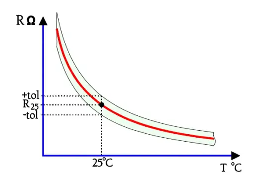
Figure R5-3. Thermistor tolerances at the reference temperature T25.
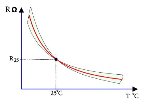
Figure R5-4. B tolerance effect.
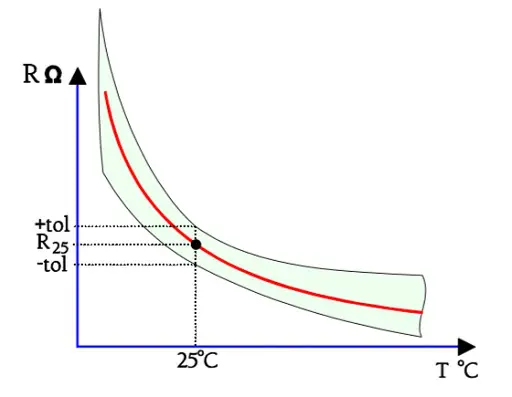
Figure R5-5. The combined effect of the R25 and B tolerances.
For more accurate applications two or more points on the Resistance/Temperature curve – abbreviated R/T curve – are specified, a so called curve-tracking application. The B tolerances then are of less importance. The tolerances of such a two or three point sensor may be stated either as a resistance deviation ∆R in percent of R or as a temperature deviation ∆T in °C, at the temperatures in question (Figure R5-6). In the latter case we have to calculate ∆R by means of the temperature coefficient α in the Formula R5-3.
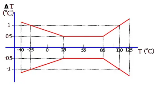
Figure R5-6. Example of alternative tolerance specification by means of a so called butterfly curve.
Slope and Temperature coefficient
The slope of the R/T curve for an NTC thermistor is determined by the B value. Sometimes the temperature coefficient a is also specified. If we derive the expression in Equation R5-1 we obtain:
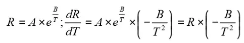
Compared to the Formula R1-4, where TCR = 1/R x ∆R/∆T, we find the same basic expression as for α. As follows from Equation R5-3 α varies strongly with temperature. Around 25 °C α usually has values between –3 and –5.5%/°C. Yet another way of specifying the slope of the R/T curve is by using resistance ratios. For example the ratios of R0/R50 or R25/R125 are compared. The ratios are stated with tolerances.
R 5.1.3 Self-heating effects
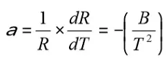
The self-heating of the NTC thermistor influences the resistance. If we apply a voltage over the thermistor the current at the beginning rises linearly according to Ohm’s law. But as soon as the internal power generates palpable heat the resistance starts decreasing. Further voltage rises gradually force resistance reductions that occur faster than the current increases. The V/I curve starts declining (Figures R5-7 and R5-8).
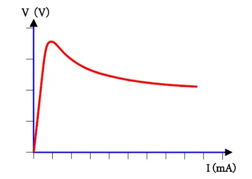
Figure R5-7. The self-heating effect on the V/I curve of an NTC thermistor
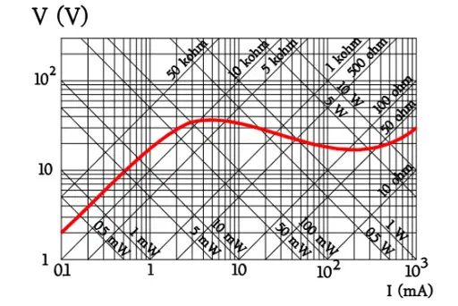
Figure R5-8. NTC thermistor example of the V/I diagram in log-log scale together with power and resistance grading.
The example in Figure R5-8 helps us realize how the parameters V, I, P and R belong together.
R 5.1.4
• Thermal cooling time constant, t
• Heat capacity, H
• Dissipation factor, D
Another two parameters are associated with Figure R5-8, namely, time and temperature. Size, shape and surrounding medium influence the velocity with which the temperature is changed. A measure of the change velocity is the thermal time constant, t. It is specified for an in-still-air freely mounted thermistor body under zero power conditions and is defined as the time required for the temperature to change by 63.2% – exactly (1-1/e) – of the difference ∆T between the initial and final body temperature, T0 respectively T∞ (Figure R5-9).
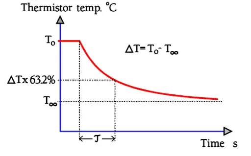
Figure R5-9. Time constant t of an NTC thermistor
With designations from Figure R7-9 the thermistor temperature can be written:
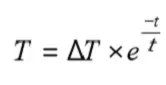
t also can be deduced from two material constants, the heat capacity H (J/°C) and the dissipation factor D (mW/°C).

The heat capacity describes how many Joules (Ws) that have to be conveyed to the thermistor body in order to rise its mean temperature by 1 °C. The dissipation factor D is expressed in mW/°C (or mW/K) and is specified as the power that raises the mean temperature of a thermistor body by 1 °C (or 1 K) when freely mounted in still air. The power dissipation capability, of course, can be increased by means of fans, heat sinks or another cooling medium, for example a suitable liquid. In that case one obtains a practical time constant. If the thermistor is placed in a suitable liquid the time constant is decreased drastically. Among other things this is utilized at production control. The thermistor is immersed into a precise temperature controlled bath and thus in a very short time is conveyed to the stable measurement temperature.
R 5.1.5 Application / Choice of type
We can distinguish three main groups of applications:
1. The temperature dependence of resistance R = f(T) is utilized. The temperature then may be determined
• either by the surroundings
• or by the internal power of the thermistor.
2. The time dependence R = f(t) is utilized, i.e. we make use of the inherent thermal inertia of the material.
3. The typical NTC characteristics of the material is utilized.
When we choose a thermistor we have to consider the following requirements
• Environment and encapsulation requirements. Glass, glaze cover, lacquer/epoxy, no encapsulation.
• Temperature range.
• Shape and design. Chip/SMD, rod, disc or bead thermistor.
• Soldering, spot welding or gluing.
• Reference temperature R25 and temperature coefficient α (-B/T2).
• Tolerance requirements on R25 and B value. Is it a point-matching or a curve-tracking R/T application?
• Power dissipation a) without perceptible heating. b) with maximum change in resistance value.
• Thermal time constant τ.
Linearizing the R/T characteristic
If we want a temperature dependence with a particular slope of the R/T characteristic over a broader temperature range, it is usually difficult to find a suitable curve shape. However, by means of fixed resistors combined with the thermistor it is possible to adjust the R/T curve in a desired direction. Figure R5-10 shows some examples of simple circuits to do this.
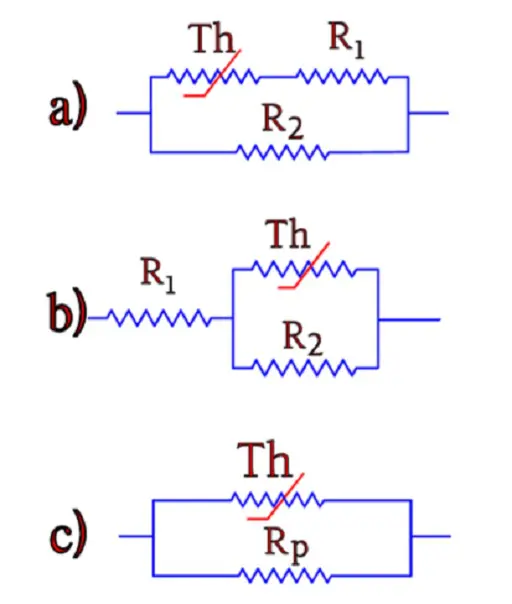
Figure R5-10. Correction circuits for the R/T characteristic of NTC thermistors.
With alternative c) one may obtain an interesting solution by dimensioning Rp according to Equation R5-6 below. The resulting parallel resistance gives a curve that intersects a straight line in three points, as shown in Figure R5-11.
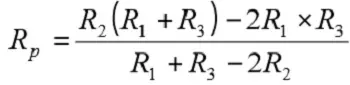
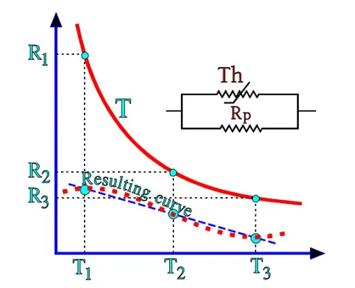
Figure R5-11. Linearizing the R/T curve of an NTC thermistor.
R 5.1.6 Failure modes
Thermistors often have very small sizes and high resistance values. They are sensitive to every “disturbance” in the material. An exposed part of the body is the terminal area, especially for small sizes. If the body isn’t encapsulated in such a manner that any lead bendings are mechanically unloaded before entrance to the thermistor body, it is easy to create small cracks around the lead entrance. With those cracks, the resistance is changed; there also is left a way for moisture and liquids to penetrate the body.
Glaze covered beads and uncoated discs with terminals soldered direct on top of metallized pads are examples of vulnerable designs. Uncoated disc thermistors are not recommended for use in conductive liquids and aggressive gases. The sintered material sometimes undergoes settlings in the crystalline structure. Such events manifest themselves as sudden resistance changes in the magnitude of 3 to 10 % and may be released by heat, temperature changes and mechanical shocks. The failure rate for non-treated delivery lots varies between 30 to 60 %. The cure is a burn-in process that usually is performed as a heat treatment.
Bead thermistors encapsulated in a melted glass body often have small sizes and corresponding thin leads, consisting of alloys that often are difficult to solder. In such events leads intended for spot welding may be the only solution. Caution. Never try to connect NTC thermistors in parallel in order to increase the power dissipation capability. The thermistor that for the moment has the lowest resistance will get a higher current load, a stronger self-heating, a greater resistance decrease, an even higher current load etc., until the avalanche effect will destroy the component.
R 5.1.7 Reliability
The reliability of NTC thermistors today is regarded as good. It depends not least on serious manufacturers with Statistical Process Control (SPC) based programs for manufacture and verified type qualifications. If we determine that the components are burn-in treated and if we purchase them with hermetic seals, i.e. glass or glass/metal housings, the reliability of such thermistors should be classified in the same group as fixed metallized film resistors.
SMD thermistors eliminate some of the problems connected with sensitive lead terminals. In the beginning there were some solderability problems but today they may be regarded as overcome. We now have got a component that structurally resembles the ceramic chip capacitor, however, with fewer sources of error. The stratified low resistance variant has its electrodes embedded in the material and may from a reliability aspect be comparable to the homogeneous type.
Nuclear radiation
Tests with radioactive radiation in the form of neutron, β and γ radiation show that thermistors are capable of withstanding high intensities without any effects on the characteristics.
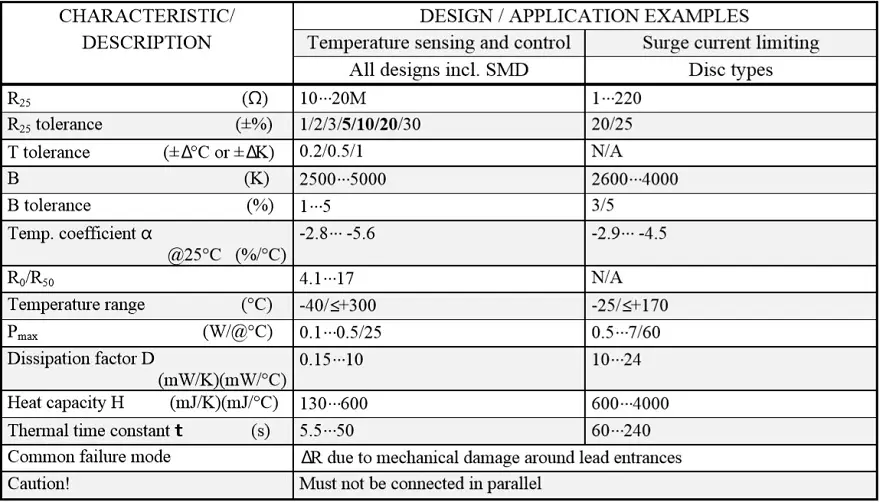
Table R5-1. NTC THERMISTORS
ABC of CLR: Chapter R Resistors
Non-linear resistors
EPCI licenced content by:
[1] EPCI European Passive Components Institute experts original articles
[2] CLR Passive Components Handbook by P-O.Fagerholt*
*used under EPCI copyright from CTI Corporation, USA

This page content is licensed under a Creative Commons Attribution-Share Alike 4.0 International License.


Discussion about this post