


")


According to IEC precision potentiometers are classified as Type 1. They exist in both bushing mount styles and in servo applications. In the latter case high demands are made for rotational life and low torque. Such potentiometers are supplied with ball bearings. If they in addition are sealed against moisture this will influence the torque. The solution of such problems implies explicit requirement specifications and close cooperation with prospective manufacturers. For very severe environments there exist,
among other things, oil-filled potentiometers.
R 4.3.1 Wirewound, Type 1
Wiper current Resistance elements formed from metal always form oxides on the surface that the wiper has to break through in order to establish electrical contact. The break through may be carried out by movement wear and by means of electrical voltage. If the potentiometer operates at dry circuit conditions, i.e., 10⋅⋅⋅30 mV and wiper currents less than 10 µA, this will make the contact more difficult and increase the noise disturbance. The schematic for a cermet potentiometer in Figure R4-15 also is applicable to wirewounds.
The disturbances also increase at decreasing temperatures and seem to be still more pronounced when the temperature is below –30 °C. Thus, the wiper requires a certain current in order to get a noise free operation, preferably more than 0.1 mA. Lubricants In order to reduce the wear and prevent oxidation, both on track and wiper, the track is in most cases lubricated with some kind of grease or oil. Most common are silicone compounds where the viscosity is relatively constant over a broad temperature range. The silicones, however, show a rapidly increasing viscosity when greases reach temperatures below –5⋅⋅⋅ -15 °C and oils below –30⋅⋅⋅ -40 °C. In addition at a moderate wiper speed the wiper tends to slide on top of the lubricant film, causing the ENR values to rise unacceptably. Silicone lubricants have a characteristic that in certain applications may be disastrous to the surroundings: they “creep”.
Their surface tension is so low that the lubricant “wets” adjacent surfaces that are contaminated with a thin film. We talk about a silicone infection. A small dab of grease will within months spread over square meter large areas. The phenomenon causes problems in following ways:
• Contaminated surfaces might be electrically isolated by the lubricant film at dry circuit conditions.
• Contaminated contacts with a breaking function accompanied by arc overs, will be isolated by the silicone granules that are formed when the miniature arcs decompose the silicone film.
• Contaminated lens systems in high energy lasers will have their lens surface damaged by the laser beam when it burns the silicone film.
• Gluing of components on contaminated surfaces is made impossible.
Single-Turn
Figure R4-30 depicts a typical single-turn servo potentiometer. There are precision styles for bushing mount applications and there exist two designs: with and without end-stops. The latter is called continuous which means, an electrical discontinuity occurs when the wiper traverse the non-conductive gap located between the ends of electrical continuity travel. The resistance wire sometimes consists of gold-platinum alloys. They are used where the contact pressure of the wiper has to be low and oxide formations minimized, for example in gyro potentiometers.
Multi-Turn
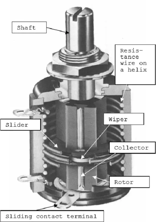
Figure R4-31. Cutaway view of a multi-turn bushing mount potentiometer. Bourns.
If we, on a thick isolation lacquered copper wire wind a resistance wire, and bend this “wire bobbin” into a helix we obtain a resistance element for a multi-turn potentiometer, as shown in Figure R4-31. This helical element then is fitted in a housing and connected to terminals. The shaft is supplied with a sleeve with a longitudinal spline and an electrical contact track.
On this rotor a slider then travels that makes contact both with the track and the resistance helix. The slider also is supplied with cams that trace against the inner side of the housing and move the slider along the rotor when shaft is turned. The common number of turns is 3, 5 or 10 but higher numbers exist. The electrical angle is usually defined in multiples of the number of turns. Thus, a 10 turn has the angle 3600°. That means, among other things, that the resolution becomes better and the setting accuracy greater.
4.3.2 Hybrid potentiometers
If the resistance wire of a multi-turn potentiometer is coated with conductive plastic as shown in Figure R4-32 we have a combination element of wire and plastic, a so called hybrid, that makes possible a multi-turn construction with conductive plastic. There are certain benefits with the smooth conductive plastic surface and the current capability of the embedded wire but the construction is, of course, more expensive than that of a conventional multiturn wirewound potentiometer.
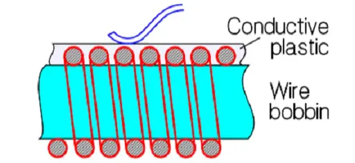
Figure R4-32. Principle of the hybrid element.
Lubricants on the hybrid track are necessary. Otherwise the track will be worn down after a small fraction of the specified rotational life. The principle for multi-turn constructions as shown in Section 2.3.1 might be applied on conductive plastic (CP) if the lacquer isolated copper wire bobbin is directly coated with CP. Use of this process, however, is quite exceptional.
4.3.3 Non-wirewounds, Type 1
Normally non-wirewound precision potentiometers are manufactured as single-turn devices. Except for conductive plastic cermet is used, as well bushing mount styles, in servo applications. The design from Figure R4-30 could as well be applicable to a nonwirewound servo potentiometer. Just as in servo applications the rotational life has to be high and puts high demands on the wiper design, the contact pressure and the track which therefore has to be polished. The polished CP track allows a number of revolutions of several tens of millions.
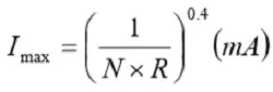
Then, however, the wiper current must be limited. Otherwise a kind of welding effects on the contact surfaces along the track results, that will destroy both wiper and surface and increase wear and noise. The wiper current should be limited to maximum of 0.25 mA. Example: A serious manufacturer promised a rotational life of 100 x 106 revolutions at 2 mA. But he recommended a maximum wiper current of 10 µA! The 0.25 mA rule, however, is not unconditional. Material, resistance value, nominal power and the number of revolutions of the rotational life come into play. The wiper current in wirewound and cermet potentiometers should comply with Formula R4-2, while hybrid and conductive plastic potentiometers should have a wiper current, Imax, according to Equation R4-3.
The contact function of cermet potentiometers is in its nature suggestive of that of the metals. Therefore the wiper current should, just as in wirewounds, also be limited in low values. An approximate minimum value might be 25 µA. (Figure R4-15). In the summary tables some guiding formulas are stated.
R 4.3.4 Linear motion potentiometers
A parallel to the slider potentiometer mentioned in section R4.2.2 but in Type 1 design are the linear actuated precision potentiometers or linear position transducers. Thus, they have a straight resistance track and a piston or guide bar that holds the wiper and transforms linear motions. The mechanical travels vary between 10 mm and 1.2 m. The resistance tracks are made of wirewound or hybrid elements, of cermet or conductive plastic. As to other parameters they have the same characteristics and specifications that apply to corresponding rotary potentiometers.
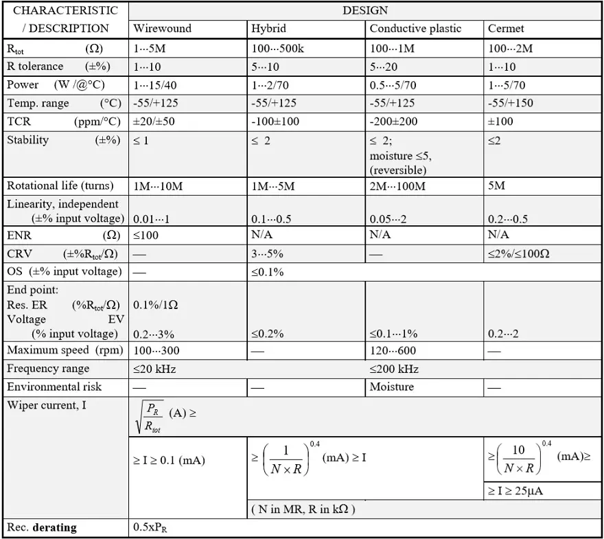
Table R4-2. PRECISION POTENTIOMETERS / TYPE 1 POTENTIOMETERS
ABC of CLR: Chapter R Resistors
Potentiometers – Precisison potenciometers, type 1
EPCI licenced content by:
[1] EPCI European Passive Components Institute experts original articles
[2] CLR Passive Components Handbook by P-O.Fagerholt*
*used under EPCI copyright from CTI Corporation, USA

This page content is licensed under a Creative Commons Attribution-Share Alike 4.0 International License.


Discussion about this post