• Latest
  • Trending
Solid Aluminum Electrolytics with Manganese Dioxide (obsolete)

Solid Aluminum Electrolytics with Manganese Dioxide (obsolete)

Inductor Resonances and its Impact to EMI

Inductor Resonances and its Impact to EMI

Dr. Tomas Zednicek Vision for Europe 2025 Passive Electronics Market

Dr. Tomas Zednicek Vision for Europe 2025 Passive Electronics Market

Littelfuse Releases Industry-First SMD Fuse with 1500A Interrupting Rating at 277V

Littelfuse Releases Industry-First SMD Fuse with 1500A Interrupting Rating at 277V

TDK Unveils Industry Highest Rated Current Multilayer Chip Beads

TDK Unveils Industry Highest Rated Current Multilayer Chip Beads

Vishay Releases Automotive SMD Thick Film Power Resistor for Enhanced Protection Against Short Transient Pulses

Vishay Releases Automotive SMD Thick Film Power Resistor for Enhanced Protection Against Short Transient Pulses

Developing Low Inductance Film Capacitor using Bode 100 Analyzer

Developing Low Inductance Film Capacitor using Bode 100 Analyzer

Highly Reliable Flex Rigid PCBs, Würth Elektronik Webinar

Highly Reliable Flex Rigid PCBs, Würth Elektronik Webinar

Würth Elektronik Releases High Performance TLVR Coupled Inductors

Würth Elektronik Releases High Performance TLVR Coupled Inductors

Causes of Oscillations in Flyback Converters

Causes of Oscillations in Flyback Converters

YAGEO Extends Rectangular Aluminum Electrolytic Capacitor Family

YAGEO Extends Rectangular Aluminum Electrolytic Capacitor Family

  • Home
  • ABC of CLR
    • All
    • ABC of Capacitors
    • ABC of Inductors
    • ABC of Resistors
    • Mounting Guidelines
    RF Inductors and Filters

    RF Inductors and Filters

    Power transformers

    Power transformers

    Telecom transformers

    Telecom transformers

    LAN transformers

    LAN transformers

    Transformer Calculation and Applications

    Transformer Calculation and Applications

    Power Inductors 2 (cont.)

    Power Inductors 2 (cont.)

    Power inductors

    Power inductors

    Current compensated chokes

    Current compensated chokes

    Coil with ferrite

    Coil with ferrite

    • ABC of Capacitors
    • ABC of Inductors
    • ABC of Resistors
    • Mounting Guidelines
  • e-Symposium
  • EPCI Membership
  • About
No Result
View All Result
European Passive Components Institute
  • Home
  • ABC of CLR
    • All
    • ABC of Capacitors
    • ABC of Inductors
    • ABC of Resistors
    • Mounting Guidelines
    RF Inductors and Filters

    RF Inductors and Filters

    Power transformers

    Power transformers

    Telecom transformers

    Telecom transformers

    LAN transformers

    LAN transformers

    Transformer Calculation and Applications

    Transformer Calculation and Applications

    Power Inductors 2 (cont.)

    Power Inductors 2 (cont.)

    Power inductors

    Power inductors

    Current compensated chokes

    Current compensated chokes

    Coil with ferrite

    Coil with ferrite

    • ABC of Capacitors
    • ABC of Inductors
    • ABC of Resistors
    • Mounting Guidelines
  • e-Symposium
  • EPCI Membership
  • About
No Result
View All Result
EPCI
No Result
View All Result
Home ABC of CLR ABC of Capacitors

Solid Aluminum Electrolytics with Manganese Dioxide (obsolete)

January 21, 2022
Reading Time: 7 mins read
A A
Solid Aluminum Electrolytics with Manganese Dioxide (obsolete)

C 3.4 SOLID ALUMINUM ELECTROLYTICS (SAL) with MANGANESE DIOXIDE (obsolete capacitor technology)

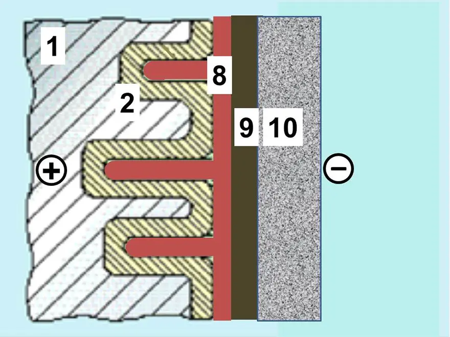
The SAL are aluminum electrolytic capacitors with anodic oxidized aluminum oxide as dielectric and with the semiconducting solid manganese dioxide as electrolyte. They are made of etched and formed aluminum anodes, which are folded for the dipped pearl types or wound into a roll for the axial style. The solid manganese dioxide electrolyte is formed onto this roll in a pyrolytic process, similar to that for solid tantalum capacitors.

SAL-capacitors were developed and introduced in the market in the 1960s by Philips. Up until December 30, 2015, it was a single source product manufactured by Vishay.

As of December 31, 2015 the SAL are end-of-life and have ceased production. Nevertheless, we still list the technology features here for comparison and overview.

C 3.4.1 Introduction

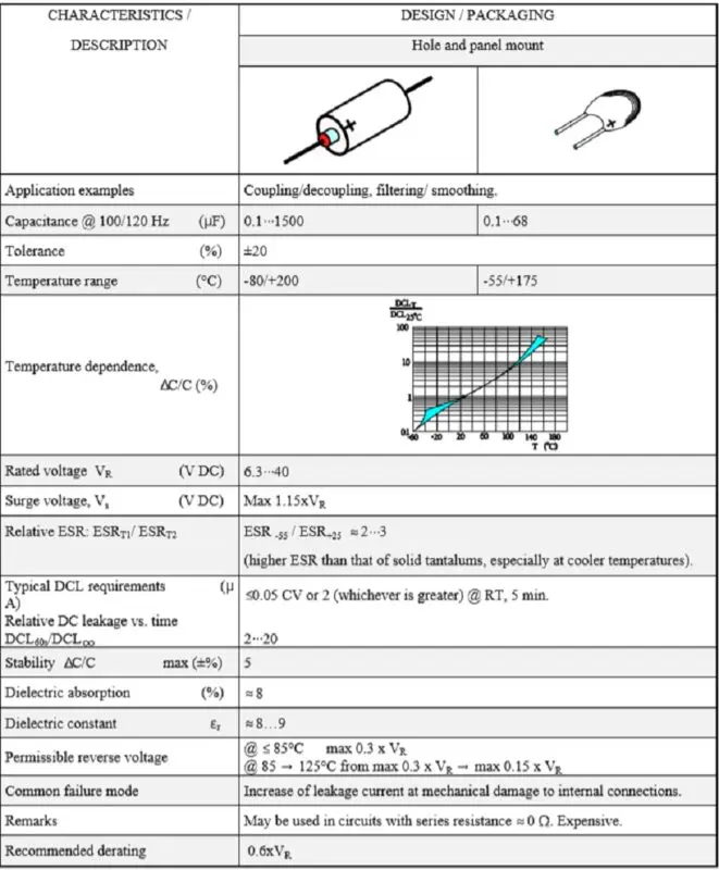
The electrolyte is a solid one. Thus, life is independent of drying effects and leakage currents and theoretically unlimited. Storage has no impairing effect on the dielectric. The stability is much better than that of wet types. The capacitance tolerance is ±20%. The price is high.… Compared to solid tantalums the price for solid aluminum (Al) electrolytics of the same CV product is between two and three times higher. The solid electrolyte doesn’t penetrate the pores of the highly etched aluminum foil equally well as a wet one. Its conductivity, however, is between one and two orders of magnitude larger than that of the wet electrolyte and its temperature dependence smaller.

Principle cross section of a SAL capacitor with solid manganese oxide electrolyte, graphite/silver cathode connection, 1: Anode, 2: Al2O3, 8: MnO2, 9: graphite, 10: silver; source: Vishay

Thus, the solid Al electrolytic is relatively insensitive to the pore effect that in wet Al electrolytics creates a deep network of series and parallel resistances as was shown in Figure C3-13. The capacitor can’t stand any breakdowns. This requires large margins between the forming and rated voltages. The forming rate usually is 2 to 3 times and the rated voltage maximum 40 V DC. Unlike solid tantalums the capacitor is relatively insensitive to pulse loads which, among other things, depends on its higher ESR that reduces the need for an additional circuit impedance.

Nevertheless, just as in solid tantalums, very high pulse currents can initiate a fire. There were two construction styles on the market, the epoxy encapsulated radial types for maximum 175 °C and the axial aluminum can type designed for maximum 200 °C. The radial lead design has a stacked aluminum plate construction which renders a very low ESL (equivalent series inductance). It ranged from 9 to 20 nH. The cylindrical can has a winding of anode and cathode foils plus glass fiber spacers. The reliability of the cylindrical can types is high. Of these there are designs with epoxy fillings intended for extreme acceleration and shock stress.

C 3.4.2 Properties

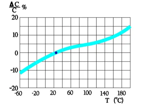
Capacitance versus temperature

Both the radial and the axial lead types are represented in Figure C3-36.

Figure C3-36. Typical temperature dependence in a solid Al electrolytic

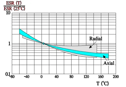
ESR versus temperature

In comparison with wet aluminum electrolytics (Figure C3-28) ESR of the solid ones have a less pronounced temperature dependence as shown in Figure C3-37.

Figure C3-37. Normalized ESR versus ambient temperature in solid Al electrolytics with different temperature ranges. Reference ESR at 25 °C

ESR versus frequency Typical normalized diagrams are shown in Figure C3-38 and 39. The former concerns the radial lead designs with their lower ESL and higher operating frequency range.

Figure C3-38. Normalized ESR versus frequency in solid Al electrolytics with radial leads. Reference ESR at 100 Hz

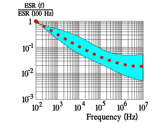
Note the lower frequency range of the following axial lead design. The steeper slope of the diagrams in the lower part of the frequency range depends on the oxide losses (Figure C3-39).

Figure C3-39. Normalized ESR versus frequency in solid Al electrolytics with axial leads. Reference ESR at 100 Hz

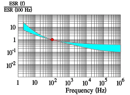
The ESR characteristics are poorer than those of solid tantalums, especially at cooler temperatures. In other word the impedance curve levels off and touches the ESR bottom at lower frequencies in solid Al electrolytics of comparable sizes.

Leakage current versus temperature

Figure C3-40. Normalized leakage current versus temperature in solid Al electrolytics. DCL reference at 25 °C

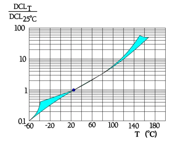
In Table C3-2 we referred to standards and depicted time to reading to 5 minutes. Figure C3-22 shows a comparison between the time dependence of solid and wet tantalums. In the solid type the curve levels out relatively quick. The same also applies to solid Al electrolytics. Thus, DCL often is measured already after 15 seconds or 1 minute.

C 3.4.3 Reverse voltage

The permissible reverse voltage is stated to be:

  • @ ≤ 85°C max 0.3 x VR
  • @ 85 → 125°C from max 0.3xVR → max 0.15xVR

C 3.4.4 Failure modes

Epoxy-dipped types with radial leads are sensitive to mechanical forces applied on the leads at mounting. Inappropriate handling results in an increase of the leakage current.

Table C 3-7. SOLID AL ELECTROLYTICS, POLARIZED, WITH MANGANESE DIOXIDE

ABC of CLR: Chapter C Capacitors

Solid Aluminum Electrolytics with Manganese Dioxide (obsolete capacitor technology)

EPCI licenced content by:

[1] EPCI European Passive Components Institute experts original articles
[2] CLR Passive Components Handbook by P-O.Fagerholt*

*used under EPCI copyright from CTI Corporation, USA

Creative Commons License

This page content is licensed under a Creative Commons Attribution-Share Alike 4.0 International License.

see the previous page:

Wet Aluminum Electrolytics

< Page 19 >

see the next page:

Solid Al Electrolytics with Conductive Polymer or TCNQ Salt

Previous Post

Wet Aluminum Electrolytics

Next Post

Solid Al Electrolytics with Conductive Polymer or TCNQ Salt

Related Posts

RF Inductors and Filters
ABC of CLR

RF Inductors and Filters

Power transformers
ABC of CLR

Power transformers

Telecom transformers
ABC of CLR

Telecom transformers

Categories

  • ABC of CLR
    • ABC of Capacitors
    • ABC of Inductors
    • ABC of Resistors
    • Mounting Guidelines
  • e-Symposium
    • ESA SPCD
    • PCNS
  • EPCI news
  • Market Insights
  • news collection
  • Transformer: Parasitic parameters and equivalent circuit

    Transformer: Parasitic parameters and equivalent circuit

    0 shares
    Share 0 Tweet 0
  • Transformer Calculation and Applications

    0 shares
    Share 0 Tweet 0
  • Introduction to Ceramic Capacitors

    0 shares
    Share 0 Tweet 0
  • Simulation with LTspice

    0 shares
    Share 0 Tweet 0
  • Dielectric Insulation Resistance, Capacitor DCL Leakage Current and Voltage Breakdown

    0 shares
    Share 0 Tweet 0

© 2024 European Passive Components Institute

No Result
View All Result
  • Home
  • ABC of CLR
    • ABC of Capacitors
    • ABC of Inductors
    • ABC of Resistors
    • Mounting Guidelines
  • e-Symposium
  • EPCI Membership
  • About
This website uses cookies. By continuing to use this website you are giving consent to cookies being used. Visit our Privacy and Cookie Policy.
Go to mobile version