


")


by Luca Primavesi (1) and Saverio Latorrata (2)
1) Itelcond, Settimo Milanese, Italy 2) Politecnico di Milano, Milan, Italy
presented by L.Primavesi at the 2nd PCNS 10-13th September 2019, Bucharest, Romania as paper 3.3.
Abstract
The aim of this work is to estimate the expected lifetime of a capacitor without basing reliability evaluation just on handbook based predictions. This approach is meant to overtake the non-homogeneous End of Life criteria proposed by the manufacturers and the difference between the real working condition in the application and the standardized condition of the criteria, as well.To obtain this result, the measured degradation of the electrical parameters of capacitors, such as Capacitance and ESR, is compared with a physical chemical model, whose constants are previously determined by accelerated stress tests (ASTs).
Introduction
Aluminium electrolytic capacitors are a common part in power electronics applications where electric energy storage and ripple current smoothing are required (1). However, they are among the first components to wear out in a power electronic assembly, having a failure rate that can be as big as the double of that of other components (2). Apart from the availability of the component, the main parameter driving the choice among capacitors with the same rated values is their reliability; a topic this paper aims to give a new insight about.
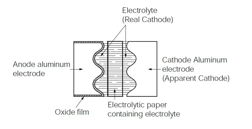
The typical aluminium electrolytic capacitor is composed by a positive pole made of an anodic foil surface (the dielectric) in contact, through a set of paper spacer, with a liquid electrolyte (the cathode) that is connected to the negative pole by means of a non-anodic foil, as schematized in Figure 1.
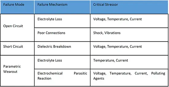
The typical failure mode and failure mechanism, see Table 1, are a function of a number of stressors depending on the ambient condition of the application the capacitor is designed and used in. Failures can be catastrophic or parametric, the first having a complete loss of functionality of the capacitor, the latter a gradual degradation.
In both cases, the main critical stressor are the capacitance drop and the Equivalent Series Resistance (ESR) rise over time (3).
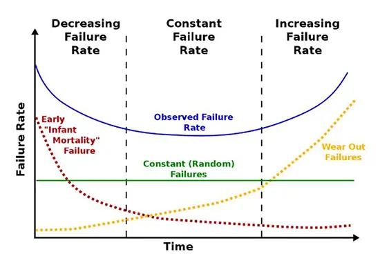
The well-known bathtub curve derives from the Weibull distribution, as shown in Figure 2, and describes the failure rate during the operational lifetime of the aluminium electrolytic capacitors (4)
To avoid catastrophic failures, manufacturers producing aluminium electrolytic capacitors always include a burn in step to intercept the early failures and they provide customers with end of life (EOL) criteria for the values of Capacitance, Equivalent Series Resistance (ESR) and Leakage Current as a ratio between the actual values and the initial values.
The two time limits defined by in-house operations that avoid early failing units to reach the market and the EOL criteria, define a constant failure rate length of time when the capacitors can be used with a statistically known failure rate. Many papers face the challenge of the remaining lifetime of a capacitor under certain operating conditions, determining various methodologies to monitor the Capacitance and Equivalent Series Resistance (ESR) values in real time and comparing it with both the initial values and the step before value (4) (5) et al. However, some criticism raised over the assumption of the constant dependency of the failure rate upon time and temperature and the successful reliability evaluation by handbook-based predictions (6).
The chosen models, and the chemical and experimental parameters within, however, miss the scope of supplying a reliable dataset of values to base a prognosis system on, in a short lapse of time. Literature suggests several methods to have an appropriate acceleration in the ageing of electrolytic capacitors (7) (8) (9); those methods are based on thermal stress either due to ambient conditions or to ripple current injection.
The most commonly accepted method is based on the thermal stress over the rated temperature of the capacitors, which is based on the application of the Arrhenius’ law to the chemical reaction speed (10). It usually consists in a cyclic profile composed by a stress period under high temperature followed by natural cooling and ambient temperature stay, before a measurement of the electrical parameters is taken (11).
A further acceleration is possible, if the capacitor is punctured. In this case, the open system permits a constant evaporation rate, increasing the ageing speed. The size and number of punctures have only marginal impact on the results (12)
Lifetime Estimation
We are providing here a suggestion that reliability and prognosis can be better estimated when the expected lifetime of a capacitor is measured in the typical ambient of its application, eventually through accelerated testing to provide a more specific standard behaviour under stress condition.
The adopted physical chemistry model recognises the role played by the electrolyte as the real cathode of the capacitor; therefore, it describes the loss of capacitance and the ESR increase as a function of the volume of the same (13).
The initial volume is equal to the paper spacer volume of the capacitor, while the vapour pressure of the electrolyte rules its variation during time, following Eq. 1 and Eq. 2.
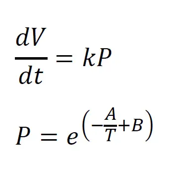
Eq. 1
Eq. 2
When estimating the vapor pressure of the electrolyte coefficient A and B can be used as it was pure solvent, accepting a small error, thanks to the fact the capacitor, even if not hermetically sealed, leaves very poor passage to gas phase. Coefficient k shows more sensitivity to the type of molecules composing the electrolyte and is therefore an experimental constant depending on the tightness of the capacitor, as well.
Factor k can depend also on operating conditions that can modify the tightness of the capacitor. The volume variation influences the capacitance in a different way than it has effect on the ESR. The capacitance is a linear function of the area of the anode surface wet by the electrolyte, being the latter
the cathode, as per Eq. 3.
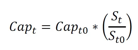
Eq. 3.
The ESR, a factor collecting all internal resistances of the capacitor, changes upon electrolyte evaporation following Eq. 4

Eq. 4.
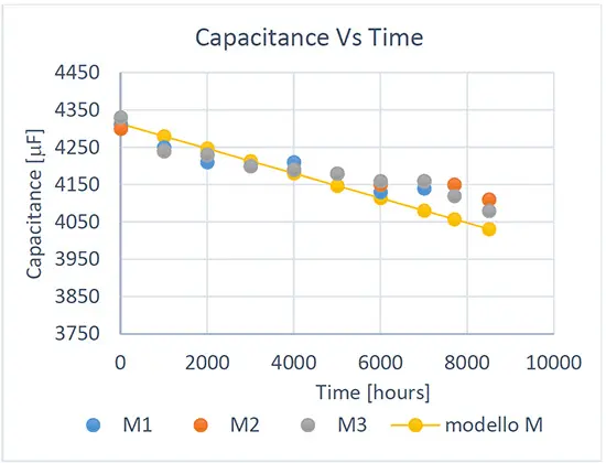
The following graphs show the results obtained comparing the chosen model to real lifetime measurements of capacitors subjected to rated conditions of voltage, temperature and ripple current. Figure 3 shows how the direct linear model based on the previous equations fits the experimental data of capacitance loss during time, while Figure 4 shows how the model of the dependence of the ESR from the volume of the electrolyte variation fits the series resistance variation. The real lifetime tests were extended well over the End of Life limit usually given to test the validity of the model when the real End of Life of the capacitor is approaching. This is intended to give a valuable model to define an accountable lower limit to base an eventual prognosis system on.
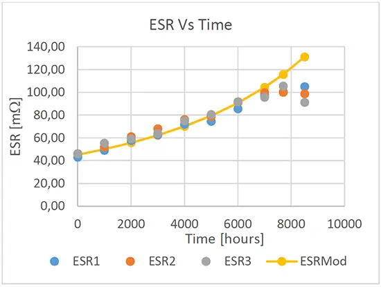
The model varies from the measured data when the ESR reaches values well over the ratio with the initial value that is considered safe; this shows that different effects than the electrolyte evaporation shall be taken into account to model the behavior of the capacitor in this region, if it is of interest.
The most probable root is the dielectric degradation caused by the degradation of the electrolyte subsequent to its evaporation; in this case, it prevents the aluminium oxide layer from continuously reforming as the model fail in predicting the capacitance drop suggests.
Test setup
The aim of this paper is to try to overcome the weak point of this methodology, which is the temperature choice, to make it available for any type of aluminium electrolytic capacitor. In fact, the vast majority of aluminium electrolytic capacitors are based on glycol as the main solvent and have boric acid as one of the solutes; the two components can react at about 150 °C to produce polyborates, which contain boric acid ester groups (14). If the test conditions create new species, they may change the evaporation curve of the electrolyte.
Then, decision is to use vacuum to keep constant the ratio of all the vapour phase fractions of the components of the electrolyte. This choice allows to consider the accelerating factor depending only from the solvent and not from the solutes, therefore to calculate the acceleration factor only once per each class of capacitors.
A heating of the capacitor at its rated temperature starts the proposed cycle, followed by a time at the same temperature. Then, the capacitor is kept under vacuum until it reaches the temperature of 50 °C; the evaporation effect below this temperature is too low. After conditioning to ambient temperature, electrical parameters are measured before a new cycle is started. Schemes of both a single pressure and a single temperature cycle are available in Figure 5 and Figure 6.
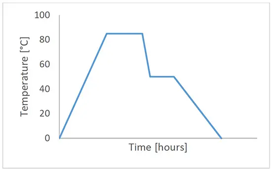
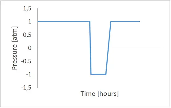
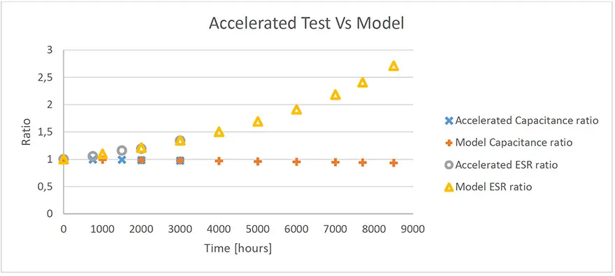
Figure 7 shows the overlapping of the results of the accelerated test, adequately stretched, with the values of the model validated before. Each measured point is the average of five different measurements on different capacitors design, from the same class.
Conclusions
Aluminium Electrolytic Capacitors are widely used and their wear out is determining the Mean Time Between Failures (MTBF) of power electronics applications; therefore, a correct estimation of their Expected Lifetime is one of the main topics when choosing amongst different products.
Reliability expectations base on non-homogeneous parameters from different suppliers and some criticism was expressed regarding the handbook-made reliability previsions.
In this article we propose a reliable physical-chemical model to predict capacitance drop and Equivalent Series Resistance rise during the operational lifetime and a method to accelerate it without losing precision.
This result is essential to compare different products, in a reasonable amount of time, with simple tools; it is also a reliable instrument for real environment lifetime estimation.
References
- J.L. Stevens, J.S. Shaffer, J.T. Vandeham. The service life of alrge aluminum electrolytic capacitors: effect of construction and application. s.l. : IEEE Transaction on Industry Application, 2002. pp. 1441-1446. Vol. 38.
- S. Yang, A. Briant, P.Mawby, D. Xiang, L. Ran and P.Tavner. An Industry-ased Survey of Reliability in Power ElectronicConverter. s.l. : IEEE Trans. on Ind. Appl, 2001. pp. 1441-1451. Vol. 47.
- Luo, J., Namburu, M., Pattipati, K., et al. Model-based Prognostic Techniques. s.l. : IEEE System Readiness Tehnology Conference, 2003. pp. 330-340. Vol. Proceedings.
- Celaya J., Kulkarni C., Biswas G., Goebel K. Towards Prognostic of Electrolytic Capacitors. 2011.
- Ladjaal K., Sahraoui M., Cardoso A.J.M., Amaral A.M.R. On-line Estimation of Aluminium Electrolytic-Capacitor Parameter Using a Modified Prony’s Method. s.l. : IEEE.
- Peter A., Das D., Pecht M. Critique of MIL-HDBK-217. Reliability Growth: Enhancing Defense System Reliability. 2015, Incorrect assumption of Constant Failure Rates.
- Sankaran, V.A., Rees, F.L. and Avant, C.S. Electrolytic capacitor life testing and prediction. s.l. : IEEE, 1997.pp. 1058-1065. Vol. 2.
- Jano, R and Pitica, D. Accelerated ageing tests for predicting capacitor lifetimes. s.l. : IEEE 17th International Symposium for, 2011. pp. 63-68.
- Celaya, J.R., et al. Accelerated aging in electrolytic capacitor for prognostics. 2012. pp. 1-6, 23-26.
- Hewitt D., Green J., Davidson J., Foster M., Stone D. Observation of electrolytic capacitor ageing behaviour for the purpose of prognostics. 2016.
- Jano R., Pitica D. Accelerated ageing tests of aluminium electrolytic capacitors for evaluating lifetime prediction models. 2012.
- Shukla R., Ahmad W., Agarwal N., Anand S. Accelerted Ageing of Aluminum Electrolytic Capacitor. 2017.
- Holman, J.P. Heat Transfer. New York : McGraw-Hill, 1973.
- Alger, M. Polymer Science Dictionary. s.l. : Springer, 2017.
- Lienig J., Bruemmer H. Fundamentals of Electronic Systems Design. s.l. : Springer International Publishing, 2017.
more 2nd PCNS symposium technical papers can be viewed and downloaded in pdf from EPCI Academy e-Proceedings:


Discussion about this post