


")


by Y. Freeman, P. Lessner, E. Jones; KEMET Electronics
presented by Ed Jones at the 2nd PCNS 10-13th September 2019, Bucharest, Romania as paper 3.2.
Commercial space constellations are an example of the increasing share of the space applications looking for more affordable electronics [1.] According to [1] selecting traditional space parts under MIL SPEC not only increases cost, but also leads to older technologies and larger packages. As an alternative, selecting parts that are not MIL SPEC, e.g., automotive parts, allows cost reduction as well as maximum flexibility including additional test requirements aligned with the program requirements. The internal evaluation by the end-user as well as usage of the application stress factors such as derating should insure reliability of the commercial parts in space application.
As it was shown in [2.], usage of the commercial (automotive) Tantalum capacitors with traditional 50% derating can be more expensive, less reliable, and less efficient solution, especially, at higher application voltages. Reference [2] cites very expensive failures related to the usage of the substandard parts in space applications.
The differences between the high reliability, special COTS, and commercial parts can be seen in the Table 1 for KEMET series of solid Tantalum capacitors.
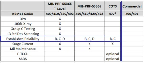
According Table 1, the major difference between MIL and Special COTS series on the left and commercial series on the right is the established reliability tests performed on every production batch. Additionally, changing materials and processes in the Hi-Rel and Special COTS parts with established reliability requires re-qualification and notifying the customers while there is no requalification required for the commercial parts.
The materials and processes in commercial parts are constantly changing to reduce the manufacturing cost and only excessive yield losses limit these changes. In this situation testing of the commercial parts by the end-user becomes unproductive since the parts from the next manufacturing lot may be different from the ones just tested.
Besides that, 50% derating of Tantalum capacitors results in about 10x increase in volume (10x loss in charge efficiency CV/cc) due to the combination of the thicker dielectric and coarse tantalum powder with lower specific surface area required to form the thicker dielectric. Increasing the capacitor size also means increasing the manufacturing cost, which depends strongly on the amount of the tantalum powder in tantalum anodes.
A possibility to achieve the highest reliability and efficiency and potentially reduce the cost of Tantalum capacitors was demonstrated in [2] for Special COTS capacitors with established reliability, which were manufactured with advanced flawless technology (F-Tech) and unique simulated breakdown screening (SBDS) described in [3].
As it was shown in [2] based on KEMET-NGC mutual work, failure rate was about 5*107 times lower with F-Tech/SBDS vs. the conventional technology. Additionally, de-rating of the F-Tech/SBDS parts provides much steeper reduction in the failure rate vs. the conventional technology. As an example, 20% de-rating of the F-Tech/SBDS parts provides more reduction in the failure rate then 50% de-rating of the Industry Average parts with conventional technology. Lower de-rating increases charge efficiency (smaller packages) and helps reduce the manufacturing cost.
Flawless dielectric (Fig. 1) is critically important for manufacturing of reliable Tantalum capacitors
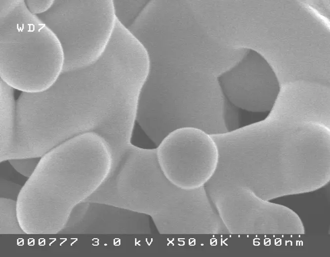
To form the flawless dielectric, tantalum anodes should have high chemical purity and mechanical robustness.3 This can be achieved by using the coarse tantalum powder pressed at high density and sintered at high temperature. At these conditions most of the impurities are evaporated from tantalum into the vacuum chamber providing high chemical purity to tantalum anodes and significant shrinkage makes the anodes mechanically strong.
The disadvantage of this old technology is low charge efficiency CV/cc, which is the major selling point of Tantalum capacitors. An alternative to the old technology is F-Tech that provides the highest chemical purity and mechanical robustness to tantalum anodes sintered with higher charge powder at much lower temperatures. In any case, it is critical to verify the quality of the dielectric by SEM analysis of the representative samples of formed anodes from every production lot. E
ven small changes to the chemical composition of the powder or process conditions can provoke initial defects in the dielectric that continue to grow during the capacitor manufacturing and testing causing failures during the field application.
The end-user processes can affect reliability of Tantalum capacitors. Several of these processes were investigated in the KEMET-NGC mutual work (Table 2).
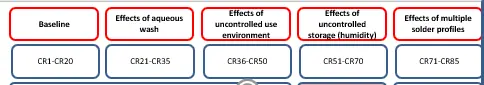
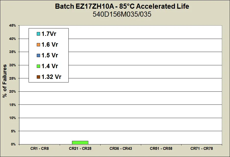
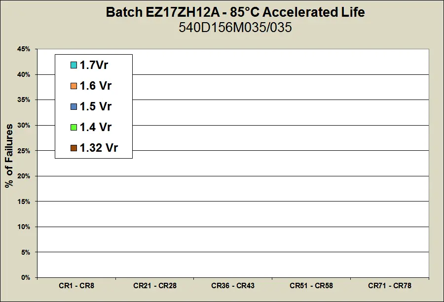
Fig. 2 demonstrates percent of failures during accelerated Life test with increasing bias voltage in D-case 15 uF – 35 V MnO2 Tantalum capacitors manufactured with F-Tech and SBDS and treated according to Table 2.
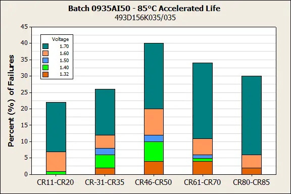
According to Fig. 2 the lowest percent of failures was in the baseline (virgin parts). The percent of failures increased with all the end-user processes, especially, with uncontrolled use environment (CR46-CR50).
Fig. 3 demonstrates the results of the same accelerated testing of Polymer Tantalum capacitors with F-Tech, SBDS and either hybrid cathode technology: in-situ PEDOT internally and slurry PEDOT externally (a), or pure slurry PEDOT internally and externally (b).
According to Fig. 3, there were practically no failures in Polymer Tantalum capacitors with F-Tech and SBDS at the same test conditions that resulted in 20% to 40% failures in MnO2 Tantalum capacitors with F-Tech and SBDS. These results show that Polymer Tantalum capacitors manufactured with advanced technologies and screening technique are more reliable than MnO2 Tantalum capacitors manufactured with these technologies and screening technique. This difference can be related to the multiple high temperature stresses during the pyrolytic deposition of the MnO2 cathode while polymer cathode is deposited and cured at much lower temperatures.
Comparison of the Polymer Tantalum capacitors with different cathode technologies was performed using SBDS results. The simulated BDV values are proportional to the actual BDV values; however, SBDS doesn’t cause any damage to the population of the capacitors. The DCL in all the parts before and after SBDS remains below the limit, and the parts with low simulated BDV are removed from the population of the capacitors after the SBDS is completed.3 Fig. 4 demonstrates simulated BDV distributions in Polymer Tantalum capacitors with hybrid (a) and pure slurry (b) PEDOT cathodes.

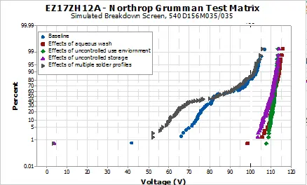
As one can see in Fig. 4, simulated BDV values are higher in Polymer Tantalum capacitors with pure slurry polymer cathode in comparison to the capacitors with hybrid polymer cathode. Pure slurry parts also had lower DCL and higher ESR in comparison to the hybrid parts. Fig. 4 also shows that the end-user processes related to humidification cause increase in simulated BDV in comparison to the simulated BDV in baseline (virgin) parts. At the same time, multiple solder profiles cause BDV values decrease in some parts with pure slurry cathodes, which can be related to the drying at the reflow testing. The effects of moisture on dc and ac characteristics of Polymer Tantalum capacitors were discussed in [3].
Conclusions
Special COTS Polymer Tantalum capacitors with established reliability manufactured with F-Tech and SBDS and used with low/no derating provide the highest reliability, efficiency, and cost effectiveness among any solid Tantalum capacitors.
Special COTS Tantalum capacitors with established reliability allow usage of the most advanced technologies and screening techniques not included in MIL SPECs
Special COTS Tantalum capacitors with established reliability allow maximum flexibility to the end-users, including additional test requirements aligned with the program requirements.
The results of the internal testing of the Special COTS Tantalum capacitors by the end-users are applicable to all manufacturing lots and dates of manufacturing; any changes to the materials and processes in these capacitors require re-qualification and notifying customers.
Acknowledgements
The authors would like to acknowledge important contributions to the experimental part of the work and helpful discussions by NGC’s Bill Winkel, Ed Rich and Payam Motabar and KEMET’s Erin Atkinson, Kristin Tempel, Steve Hussey and Jonathan Paulsen.
References
- A. Casasnovas; The Path to Affordable Electronics for Commercial Space Constellations; Honeywell, SPWG, LA, April 2019
- Y. Freeman and P. Lessner. Tantalum Capacitors in Space Applications, ESA 2018, https://passive-components.eu/tantalum-capacitors-in-space-applications/
- Y. Freeman. Tantalum Capacitors: Science, Technology, and Application, Springer, 2017
more 2nd PCNS symposium technical papers can be viewed and downloaded in pdf from EPCI Academy e-Proceedings:


Discussion about this post