• Latest
  • Trending

Energy Content and Electromagnetic Force

Würth Elektronik Launches New Line of Toggle Switches

Würth Elektronik Launches New Line of Toggle Switches

Microwave Multi Line Connectors Mounting and Handling Precautions

Microwave Multi Line Connectors Mounting and Handling Precautions

PCNS Passive Components Symposium 11-14th September 2023
Flex Suppressor Explained and its Applications

Flex Suppressor Explained and its Applications

Exploring the Benefits of High-Performance MLCC Capacitors for Aerospace and Defense

Exploring the Benefits of High-Performance MLCC Capacitors for Aerospace and Defense

Murata Establishes Joint Venture Company to Produce MLCC Raw Materials

Murata Establishes Joint Venture Company to Produce MLCC Raw Materials

Samtec New Interconnects Enhances Power and Signal Integrity

Samtec New Interconnects Enhances Power and Signal Integrity

Examining the Influence of ESR and Ripple Current on Selecting the Suitable Capacitor

Examining the Influence of ESR and Ripple Current on Selecting the Suitable Capacitor

PCB Via Design Selection; Plugging-Filling-Tenting

PCB Via Design Selection; Plugging-Filling-Tenting

SABIC Validates its 150°C Film Foil to Enable Adoption of Film Capacitors in SIC Power Modules

SABIC Validates its 150°C Film Foil to Enable Adoption of Film Capacitors in SIC Power Modules

Outlook of Passive Electronic Components Market for Oil & Gas Electronics in 2023

Outlook of Passive Electronic Components Market for Oil and Gas Electronics in 2023

  • Home
  • ABC of CLR
    • All
    • ABC of Capacitors
    • ABC of Inductors
    • ABC of Resistors
    • Mounting Guidelines

    RF Inductors and Filters

    Power transformers

    Telecom transformers

    LAN transformers

    Transformer Calculation and Applications

    Power Inductors 2 (cont.)

    Power inductors

    Current compensated chokes

    Coil with ferrite

    Trending Tags

      • ABC of Capacitors
      • ABC of Inductors
      • ABC of Resistors
      • Mounting Guidelines
    • e-Symposium
    • EPCI Membership
    • About
    No Result
    View All Result
    European Passive Components Institute
    • Home
    • ABC of CLR
      • All
      • ABC of Capacitors
      • ABC of Inductors
      • ABC of Resistors
      • Mounting Guidelines

      RF Inductors and Filters

      Power transformers

      Telecom transformers

      LAN transformers

      Transformer Calculation and Applications

      Power Inductors 2 (cont.)

      Power inductors

      Current compensated chokes

      Coil with ferrite

      Trending Tags

        • ABC of Capacitors
        • ABC of Inductors
        • ABC of Resistors
        • Mounting Guidelines
      • e-Symposium
      • EPCI Membership
      • About
      No Result
      View All Result
      European Passive Components Institute
      No Result
      View All Result
      Home ABC of CLR ABC of Capacitors

      Energy Content and Electromagnetic Force

      January 21, 2022
      Reading Time: 5 mins read
      29 2
      A A

      C1.4 ENERGY CONTENTS / FORCE MANIFESTATIONS

      C 1.4.1 Energy contents

      The energy stored in a capacitor can be described as
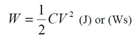
      This image has an empty alt attribute; its file name is EQ-C1_20.jpg

      ……………[C1-20]

      C 1.4.2 Force action

      from electromagnetic fields

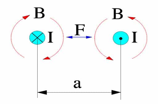
      Parallel current carrying conductors are surrounded by magnetic fields exerting forces on each other. If currents flow in the same direction the fields (and the conductors) attract each other. If the current flows in opposite directions as in the Figure C1-24 they are repelling each other.

      Figure C1-26. Magnetic force action, F, between conductors with a current flow, I. B = magnetic flux density

      If

      • the conductor length l is expressed in m,
      • the current I is expressed in A and
      • the distance a is expressed in m,

      the force per meter between the conductors will be
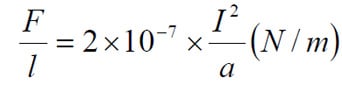
      This image has an empty alt attribute; its file name is EQ-C1_21.jpg

      ………………………[C1-21]

      According to the formula (C1-1) Q = C x V (As). If this expression is derived we obtain dQ/dt = I = C x dV/dt (A).

      Pulse loads are not unusual, especially in conditions with high voltage gradients, and thus high charging currents also occur which might cause appreciable magnetic fields between close lead patterns, for example.

      C 1.4.3   Force action in electrostatic fields

      Capacitors are typical examples of applications where electrostatic fields are applied. These fields can generate significant mechanical forces­. If we know the electrode distance d (m) it’s easy to determine the electric field strength E (V/m). Then we can outline the force per unit area, i.e. the pressure that the electrodes exert on the dielectric.

      This image has an empty alt attribute; its file name is EQ-C1_22.jpg

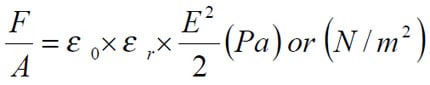
      ……………………………….. [C1-22]

      Example. Suppose we have an oil impregnated paper capacitor with r = 5 and the dielectric = 15 m (0.6 mils) which is loaded with 250VAC. Then the instantaneous maximum pressure will be
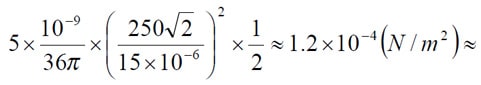
      This image has an empty alt attribute; its file name is EQ-C1_22b.jpg

      0.1 kp/cm2 !

      If we instead calculate on a 35 V solid tantalum capacitor with a typical and approximate dielectric thickness of 0.2 mm (0.008 mils) the formula gives at 30 V DC a pressure of
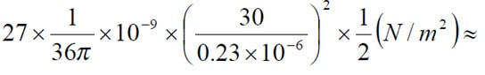
      This image has an empty alt attribute; its file name is EQ-C1_22c.jpg

      2 N/mm2 !

      It is difficult to determine how much the dielectric is influenced by such forces, especially when the electrodes have such complex configurations. Electrostatic action of such forces here is of vital importance.

      featured image credit: sdsu-physics.org


      ABC of CLR: Chapter C Capacitors

      Energy Content and Electromagnetic Force

      EPCI licenced content by:

      [1] EPCI European Passive Components Institute experts original articles
      [2] CLR Passive Components Handbook by P-O.Fagerholt*

      *used under EPCI copyright from CTI Corporation, USA

      Creative Commons License

      This page content is licensed under a Creative Commons Attribution-Share Alike 4.0 International License.

      see the previous page: Capacitor Losses (ESR, IMP, DF, Q)

      < Page 4a >

      see the next page: Ripple Current and Power Load

      Previous Post

      Core Materials and Their Losses

      Next Post

      Ripple Current and Power Load

      Related Posts

      ABC of CLR

      RF Inductors and Filters

      850
      ABC of CLR

      Power transformers

      695
      ABC of CLR

      Telecom transformers

      541

      Categories

      • ABC of CLR
        • ABC of Capacitors
        • ABC of Inductors
        • ABC of Resistors
        • Mounting Guidelines
      • e-Symposium
        • ESA SPCD
        • PCNS
      • EPCI news
      • news collection

      Popular Posts

      • Transformer: Parasitic parameters and equivalent circuit

        1212 shares
        Share 485 Tweet 303
      • Transformer Calculation and Applications

        662 shares
        Share 265 Tweet 166
      • Simulation with LTspice

        446 shares
        Share 178 Tweet 112
      • Introduction to Ceramic Capacitors

        443 shares
        Share 177 Tweet 111
      • Insulation Resistance, DCL Leakage Current and Voltage Breakdown

        412 shares
        Share 165 Tweet 103

      EPCI Membership

      join passive components community

      © 2023 European Passive Components Institute

      No Result
      View All Result
      • Home
      • ABC of CLR
        • ABC of Capacitors
        • ABC of Inductors
        • ABC of Resistors
        • Mounting Guidelines
      • e-Symposium
      • EPCI Membership
      • About

      Welcome Back!

      Login to your account below

      Forgotten Password?

      Retrieve your password

      Please enter your username or email address to reset your password.

      Log In
      This website uses cookies. By continuing to use this website you are giving consent to cookies being used. Visit our Privacy and Cookie Policy.