source: EGGO Space s.r.o ; ESA SPCD 2018 Symposium
EPCI e-symposium library article
The Skeleton SpaceCap product development started in 2011 as part of an ESA commissioned activity to produce a capacitor based on Skeleton’s proprietary Carbide Derived Carbon material. The resulting SpaceCap product is a 100F capacitor with a very high power density of 92 kW/L. The product is now in a qualification phase concerning electrical and mechanical aspects. Radiation performance will be evaluated and qualified in potential follow up activities.
The SpaceCap product presentation will focus on product specifications, results of qualification tests conducted up to date and the equivalent capacitor model to showcase the variation in capacitance (C) and internal resistance (ESR) at different application times (from 1 microsecond to 10 seconds at various temperatures).
One of the main SpaceCap design drivers is to reach 18 years of lifetime at 20 °C at an operating voltage of 2.5 V (derated from 2.85V nominal).
Theme of the presentation will focus on comparative test results (performed by EGGO Space s.r.o) of large format supercapacitors from Skeleton Technologies and well-known competitors. All supercapacitor manufacturers use different measurement techniques making datasheet-based comparison incomparable. The test results presented have been performed according to IEC 62391 standard methods and thus provide high quality results with 10 units tested of each product.
In the tests Skeleton Technologies’ COTS supercapacitors have shown exemplary power performance due to considerably lower ESR in comparison to competing products. The ESR of the best competing product was found to be twice as high with many competitor products having an ESR nearly three times as high.
published by EPCI under approval of ESA SPCD 2018 organizing committee.
Title: Qualification of Commercial Off-The- Shelf Supercapacitors for Space Applications
Author(s): David Latif (1), Petr Vašina (1), Lukáš Diblík (1)
Organisation(s): (1) EGGO Space s.r.o , Dvořákova 328 56301 Lanškroun ,Czech Republic
Symposium: ESA SPCD 2018
Reference: Test, Reliability & Evaluation for space 3.
ISBN: N/A
e-Sessions Applications: Aerospace
e-Sessions Scope Components: Capacitors
e-Sessions Topics: Test & Measurement
Supercapacitors also called electrochemical double layer capacitors are energy storage devices storing high volume of electric energy in the double layer between a high surface area electrode and an electrolyte. As compared to batteries no chemical reactions should occur at the electrodes.
The use of supercapacitors on spacecrafts and launchers can be manifold and its use is very potential in other civil and military areas. To obtain a reliable data according to IEC 62391 resulted in development of new advanced technique in our lab.
Since, it’s essential for the any life time data assessment to have the results the one can trust. Nowadays it’s a serious issue to precisely measure the ESR values of high capacity supercapacitors from hundreds of Farads up. The reason is the very low level of ESR in order of hundreds of microohms. No AC RCL bridge we have got in our lab can measure such low values exactly. Also the results accuracy, its repeatability and reproducibility of such measurements is a nice challenge.
EGGO Company has already proved that during the previous projects of supercapacitors measurement, life assessment, qualification, modeling and bank design of the 10F cells is the right company to do so, but it’s a different story.
2. TESTED SAMPLES
For the measurement set up assessment we have chosen 4 different top manufacturers making high capacity supercapacitors of two different capacitance levels available on the market. The first capacitance level is 3000F + and the second one 1200 F. This should prove the measurement technique enough in order to rely on during the consequent reliability/life tests.
The list of selected manufacturers:
A) Skeleton
B) Maxwell
C) Nesscap
D) LS Mtron
E) IOXUS

Group – 1200 F
- 1200 F SKELETON SCA1200 1200F 2,85V 1,35Wh
- 1200 F LSUC 2,7V 1200F 1,22WhLs , Mtron Ltd
- 1200 F Maxwell Tech BCAP1200 P270 1200F 2,7V 1,2Wh
Group 3000+ F
- 3200 F SKELETON SCA3200 3200F 2,85V 3,61wh
- 3000 F IOXUS i CAP iRB3000K270CT 3000F 2,7V 3,04Wh
- 3400 F MAXWELL Tech K2SERIES BCAP3400 P285 3400F 2,85V 3,84Wh
- 3400 F NESSCAP NE03V03400SW001 3400F 3,0V 4,2Wh
- 3400 F Ls Mtron Ltd LSUC 2,85V 3400F 3,84W
3. TESTS DESCRIPTION
Initial capacity measurement methods have been applied in two specifications according to IEC 62391 and the measurement set up should be able to do so. Also the DC ESR measurements have been included into the measurement cycle. Capacitance measurement theory
Measurement method 1A
1. Constant charging current set to ICC=UR/38RN(ESR)
2. Charging up to rate voltage
3. Holding rate voltage for 30 min
4. Discharging with rate discharge current by IEC 62391
5. Time measurement span between two points U1 (0,8 UR) and U2 (0,4 UR)
Measurement method 1B
1. Constant charging current set to ICC=UR/38RN(ESR)
2. Charging up to rate voltage
3. Holding rate voltage 30 min
4. Discharging current set to ICC=UR/40RN(ESR)
5. Time measurement between two points, U1 (0,8 UR) and U2 (0,4 UR)
Simple formula how to determine capacitance from discharge region:
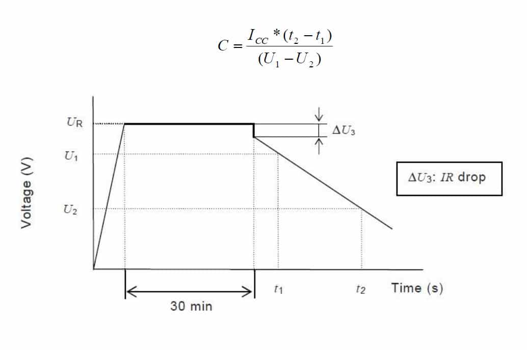
Fig.3. Time vs voltage during the capacitance measurement.
DC ESR measurement theory
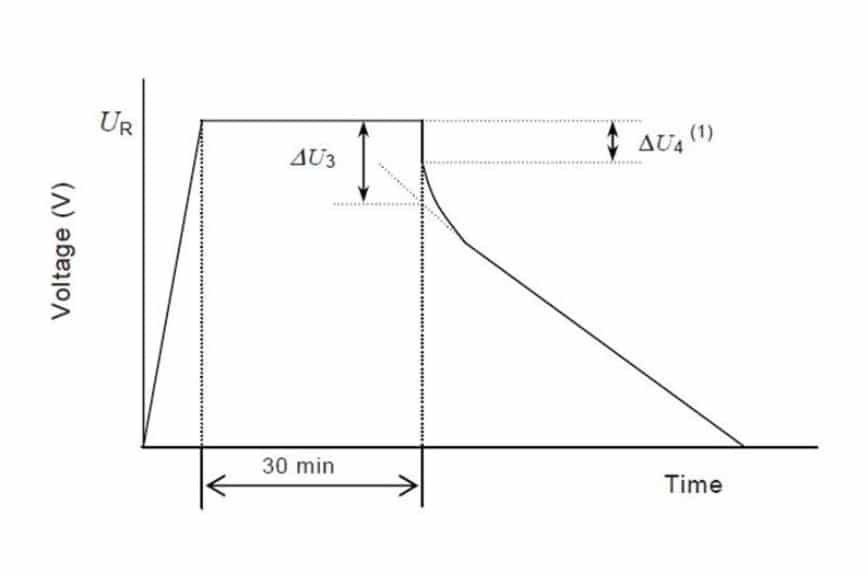
Fig.4. Time vs voltage during the ESR measurement.
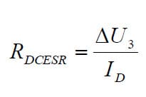
By the linear voltage versus time interpolation one can obtain inersetion where voltage drop can be calculated and DC ESR for Method 1A and Method 1B thru equation (only the ID current differs according to IEC62391) look like:
4. EXPERIMENTAL SETUP
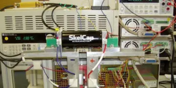
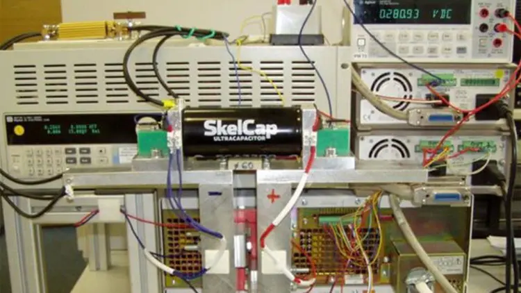
The experimental setup was the key part of the project. The setup should handle high passing currents with very low losses as well as high accuracy voltage readings with reasonable sample rates. In our setup we have used two power supplies able to deliver up to 600A and DC load able to dissipate up to 500A. Since, this is modular thing that can be upgraded either to do higher current job or work at higher voltages e.g. at capacitor banks. The first thing we had to do was to remove all ballast devices from power supplies on the outer side, because they negatively affect both capacitance and ESR measurement results.
This is simple action but than we have realized, that it’s impossible to stabilize the output voltage. Therefore temporary load has to be applied during the steady voltage conditions and must be released prior to main load activation. The other issue we have faced was the accuracy of voltage readings across the capacitor for ESR measurements, to be able to read and repeat values in
hundreds of picoohms.
You should be aware, when measure the voltage across the capacitor around rated voltage you have to use the range according to this level, but on the other hand you are loosing accuracy even if the precision meter is used. Higher precision also means slower sample rate. To overcome this point we are applying shift voltage to the meter close to the rated voltage (lower by 0.1-0.2V), which allow us to use single e.g. 0.2V measurement range. It’s essential that the four wire measurement technique has been utilized.
The last but not least part is PC software written in Keysight VEE environment. The software controls the power supplies, load and all other equipment. At the end of the measurement calculates Capacity, ESR values via mathematical treatments as well as always finds the exact time of any performed event to prevent time delays caused by control lines or PC to have an impact on result accuracy.
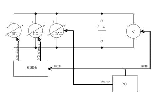 Fig.5. Simplified wiring diagram
Fig.6. Experimental setup view – see featured image
5. RESULTS
All measurements have been taken on the equipment described above and used as an input data for further testing (life testing, cycle testing…). Due to the tests are ongoing no other results can be presented within this paper.
Group 1200F
Capacitance plots
 The resulting capacity of group 1200F shows higher initial capacitance than one should expect. The highest values have the Maxwell cells up to 20% above specification.
DC ESR plots
 The ESR values for the Sceleton have three times lower ones to Maxwells and two times lower ones to LS supercapacitors. This will results in lower thermal losses during the cycle test and lower degradation caused by lower temperature.
Group 3000+F
 Once again the initial capacitance is higher than specified in datasheets.
Method 1 B 3200 + cells
 The ESR for the Skeleton cells is below 100 microohms, that is extremely good value.
6. CONCLUSION
Supercapacitors show its potential in Space applications and Skeleton is the one where its production capabilities are highly promising for future Space supplies of this kind of cells. EGGO Space Testhouse is due to this work and long time cooperation with Skeleton cells testing potential Lab for Qualification of this kind of Supercapacitors with a good know how and Lab equipment.
REFERENCES
Supercapacitor information resources:
1. www.skeletontech.com
2. www.nescapp.com
3. www.maxwell.com
4. www.ioxus.com
5. www.lsmtron.com
